


4848
GENERAL INSTRUCTIONS FOR PF
MODULAR ENCLOSURES FOR
TRANSFORMER SUBSTATIONS
IG-021-GB
version 07
29.08.2008
Page 35 of 48
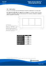
3.7.7. Transformer Protection Fences
The transformer protection fences are inserted through the roof using the crane and are
attached to the floor plate and to the front and rear panels.
Figure
3.56
Figure
3.57
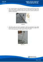
3.7.8. Covers
The covers are lowered onto the vertical panels using the crane.
Figure
3.58
Figure
3.59
Figure 3.61
Once the first roof panel is in place, and if two or more modules are being used, two
20 x 10 mm rubber strips must be inserted into the joint between the different covers, and
these must be tightly bolted together using M16 x 40 nuts and bolts.
Figure 3.60:
M16 x 40 nuts and bolts to join the covers


