


System manual
SM0974113 A 01
5
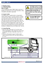
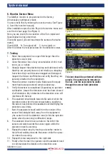
*Detection zone is approximate and will vary based on detected object and operating conditions.
Approximate Pattern Shown
12,00 m
0,60
2,40 m
8,00 m
1,60 m
6,00 m
0,90
Distance of Sensor from front vehicle;
see figure 1
Figure 2
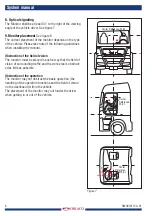
4. For the pigtail, drill a 38 mm hole for the sensor
connector and mating connector.
5. Secure the sensor to the equipment using the supplied
hardware, with a maximum 2.49 Nm torque.
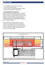
3. In
i
tial System Power Up and Test
Move the vehicle to an open space larger than the system
detection zone to test. The equipment ignition must be en-
ergized to power up the system. Activate the system. Check
if there are no moving objects in the sensor’s detection
zone and for any objects on the equipment that may be in
the sensor’s field of view. If possible, move the sensor so it
does not detect the object(s).
Test the detection zone using two people, a driver who
remains in the cab and an assistant who walks quickly
through the sensor detection zone. An accurate detection
zone can be mapped by moving about the sensor detection
zone and noting when the display buzzer activates and a
warning is shown in the display.


