


21
IM0973270 A 09
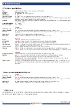
Article number: 0208691
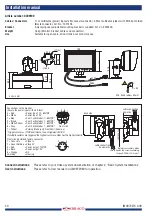
Cables / Connectors
6m power cable open wired, 6m video cable with 7p molded M16 female connector;
Art. No.: 8976331
Bracket
Anodized aluminium adjustable mounting bracket is supplied. Art. No. : 8974000
Weight
1,7kg (Monitor, bracket, cables and connectors)
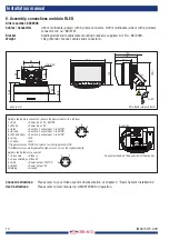
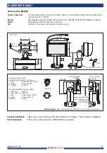
120
units in mm
188
6000
98,
3
49
,1
89
,6
105
80
54
40
∅
6,2 (4x)
Min. bend radius= 50mm
R = 50
back side
cable connection
upwards
cable connection
downwards
Note by reassembly: Make
sure to tighten the screws according
torque 0.25 Nm / 35.4 in.ozf
remove cap
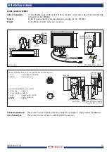
1
2
3
7
4
56
Connections to the monitor: (Secure the power input with a 5A fuse)
1 = Red
= Power input: 18...30V/DC
2 = White
= Power input: 0V
3 = Blue
= Cam No. 1 activated at 7...30V/DC*
4 = Brown
= Cam No. 2 activated at 7...30V/DC*
5 = White/Yellow = Cam No. 3 activated at 7...30V/DC*
6 = Grey
= Cam No. 4/Speedometer/Tachograph/Zoom in
7 = Yellow
= Parking Brake (only Front Cam)/Zoom out.
*Triggers camera >7V/DC and returns to non triggered <5V/DC.
If multiple cameras are triggered the highest camera number has the highest priority
.
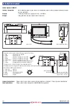
Front side 7p molded female connector:
1 = Coax core
= Video in
2 = Coax shielding = Video 0V
3 = Red
= Power output: equal to “Power input”
4 = Black
= Power output: 0V
5 = Orange
= RS232 RX
6 = Yellow
= RS232 TX
7 = Grey
= RS232 Rx & Tx 0V
Shielding
= Ground
2
5
7
4
3
6
1
Connect instructions:
Please refer to your Orlaco system documentation or chapter 2. “Basic System Installations”
User instructions:
Please refer to User manual no: UM0972080 for operation.
Installation manual


