Orlaco 0103482 Скачать руководство пользователя страница 3

IM0973112 A 07 

3

Installation Manual

1. Introduction

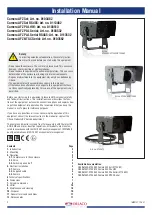
These Auto Focus Zoom (AFZ) cameras have excellent specification 

properties for maximum performance on the different workstations, such 

as cranes, emergency vehicles, vessels and military vehicles.
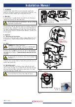
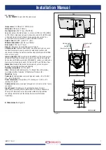
2. Mounting

A camera bracket is supplied with the Camera AFZ Alu/Sst; the package 

includes the necessary nuts, bolts and washers. 

Use of a different type of bracket or bracket made by a different 

manufacturer is not permitted.


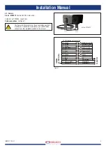
This bracket is suitable for mounting the camera in hanging, standing and 

overhead positions, see figure 1. Use a Allen key to adjust the bracket to 

the camera with M6 socket head cap screws. Use a 13-mm open-ended 

spanner to secure the camera bracket with four M8 bolts, nuts and wash-

ers. See figure 2.

3. Operation

3.1. Overpressure in the enclosure

The enclosure of the Camera AFZ is with dry-nitrogen filled and has a 1,4 

Bar overpressure, therefore IP68 according to IEC 60529 (25 m under 

water).

3.2. Valve 

WARNING:

 Do not open the enclosure.

The enclosure is protected by static pressurization (Nitrogen).

The enclosure shall be filled only by the manufacturer.

The filling valve may 

ONLY

 be used by the manufacturer. 

Do not remove 

the blue seal.

 See figure 3 

A

The warranty expires when the blue seal 

is broken!

The warranty expires when the user does not act according the 

instructions. 

If the pressure is lost send the device back to the manufacturer for inves-

tigation, repair and testing.

3.3. Switching on and off

The Camera AFZ Alu/SSt is switched on by connecting the connector 

cables to the power supply. It is switched off by disconnecting the Power 

cable from the power supply. Under normal circumstances, the system 

starts once the power is 24V/DC+/-10%.

Ensure that all parts are firmly fixed, stable and secure.

Figure 2

Figure 3

M8

M6

Attention:

Always use the

Isolation manchets


Figure 1

UNITS IN MM

  Indicator light

 (red)

Camera ON

      Indicator light


(green)

           Heating ON

(Demister 2 heater)

122

96

13

80

74,9

7,7

40

14,7

R4,5 +0,5 -0,0

10

122

141,5

109

140,2

260

122

141,5

A

A

Bracket overhead

Bracket standing

Bracket hanging

Villing valve

with blue seal

Содержание 0103482

Страница 1: ...Camera AFZ PAL Serial Camera AFZ NTSC Serial Installation Manual Manual No IM0973112 A 07 Article no 0103482 0113482 0103513 0103532 0113532 0103562 01 2016 English Art no 0103532 0113532 0103562 Art...

Страница 2: ...equipment outlines the connection options and explains how to put the equipment into operation We recommend that you keep this manual in a safe place for reference purposes If you have any questions o...

Страница 3: ...29 25 m under water 3 2 Valve WARNING Do not open the enclosure The enclosure is protected by static pressurization Nitrogen The enclosure shall be filled only by the manufacturer The filling valve ma...

Страница 4: ...ck 0V 5 Orange Serial TX 6 Yellow Serial RX 7 Grey Not connected Shielding GND 4 2 Supplied cable Art no 0304410 Cable 6 0m m7M m7F see figure 6 Electrical connections see figure 5 1 Coax Core 2 Coax...

Страница 5: ...should make connections that are not described in this manual Art no 0103513 Installation Manual 14 White black not connected 13 Green Brightness on off 12 Purple Autofocus on off 11 White 0 Lux on of...

Страница 6: ...W Communication Communication via serial interface Visca Pelco D protocol RS232 or RS485 9 6 Kbps Green Passport All materials are compliant to Green Passport requirements according IMO resolution ME...

Страница 7: ...vibrations Corrosion proof housing according to IEC 60068 2 52 salt mist cyclic Ingress protection IP68 according to IEC 60529 Dust tight and protect ed against the effects of immersion in water up t...

Страница 8: ...focus are bit encoded commands that always have bit 0 in cmnd2 set to 0 Any number of non exclusive bits may be set in the cmnd1 and cmnd2 bytes for this format of command data1 and data2 are pan and...

Страница 9: ...le Clear Preset Byte Byte 2 Byte 3 Byte 4 Byte 5 Byte 6 Byte 7 Sync addr 0x00 0x05 0x00 Preset chksm 0xff ID Preset ID valid range 0 5 Go To Preset not for TIC camera Byte 1 Byte 2 Byte 3 Byte 4 Byte...

Страница 10: ...to Factory default setting PLL send following com mands 1 8x 01 7F 01 7F FF 2 8x 01 7F 7F 02 00 00 01 08 00 FF 3 8x 01 7F 7F 02 0F 02 05 00 00 FF 4 Cycle power off on of the camera Only use this comm...

Страница 11: ...nnot be held responsible for any errors in this manual or any consequences thereof FCC compliance statement The camera comes under section for commodity codes for electronic equipment This is known as...

Страница 12: ...we have a production department ware house design department service department and showroom Vision is our mission and Orlaco therefore deploys the development manufacture supply and service of camer...

Отзывы: