2
3
Click
7.
Connect and the autoguider
and SteadyStar will connect at the
same time.
Click
8.
Connect Rotator in the
Rotator section. You will be
prompted with the
ASCOM
Rotator Chooser window
(Figure 2).
Note: You must be connected to
the autoguider camera in order to
connect to the SteadyStar and the
Rotator.
Select the
9.
SteadyStar Rotator
and click OK. The SteadyStar will
initiate the instrument rotator and
you will hear the stepper motor
move. The sound of the rotator will
vary depending on the weight of
your camera setup and the motor
speed.
You can manually jog the rotator to any
position between 0° and 359.9° simply
by entering the value in the
Rotator
section and clicking
Rotate to (Figure
3).
This function is useful when try-
ing to acquire guide stars through the
SteadyStar’s off-axis prism.
adjusting the rotator speed
and settings
You can adjust the rotator speed to pro-
vide more torque (slower) or to operate
quieter (faster).
With the rotator connected, click
1.
Setup in the Rotator section of
the SteadyStar’s
Setup tab.
In the
2.
SteadyStar Rotator Setup window (Figure 4), choose the speed you
wish to set the rotator to. For most applications, the default speed is best,
unless you want to reduce the sound by increasing the speed. Click
Set
Now.
This addendum discusses the features
of the instrument rotator built into your
SteadyStar. For software installation
and use with the SteadyStar and the
functions of the AO, please refer to the
SteadyStar manual included with this
addendum.
The SteadyStar AO Guider with Field
Rotator enables you to more easily
acquire a guide star by mechanical-
ly rotating the off-axis pickoff prism.
Additionally, if you are using a fork
mounted altitude-azimuth mount such
as a Celestron NextStar
®
telescope,
you can compensate for field rotation
and take long exposure astro-images
without an equatorial platform.
cabling and setup
Use caution as you set up your imaging equipment and keep the cables in mind
when rotating your camera and imaging accessories. Securely thread the 2"
nosepiece of the SteadyStar onto the SteadyStar body and make sure it can sup-
port the torsion caused by the potential offset weight of your imaging camera and
accessories. As a convenience, you can route cables through the loop provided
for extra security (Figure 1).
There should be a small amount of mechanical backlash in the rotator. This
ensures free movement of the rotator under different loads and conditions. The
SteadyStar utilizes anti-backlash when rotating to a given angle.
connecting to the rotator
Please follow the installation steps provided by the SteadyStar manual. Once you
have installed the SteadyStar software, you will automatically have the instrument
rotator installed in your ASCOM devices.
Connect the SteadyStar to your computer’s USB port.
1.
Plug the SteadyStar into your power source using the provided 12VDC cable.
2.
Connect the provided RJ-12 autoguide cable from the SteadyStar to your
3.
mount’s compatible autoguide port.
Connect the autoguider camera to your computer’s USB port. Make sure the
4.
autoguider camera is properly installed recognized by your computer.
Open the SteadyStar software.
5.
Select your autoguider camera in the
6.
Camera selection pulldown menu.
If you are using a video or web camera, select
Video camera then click
Choose to select your camera.
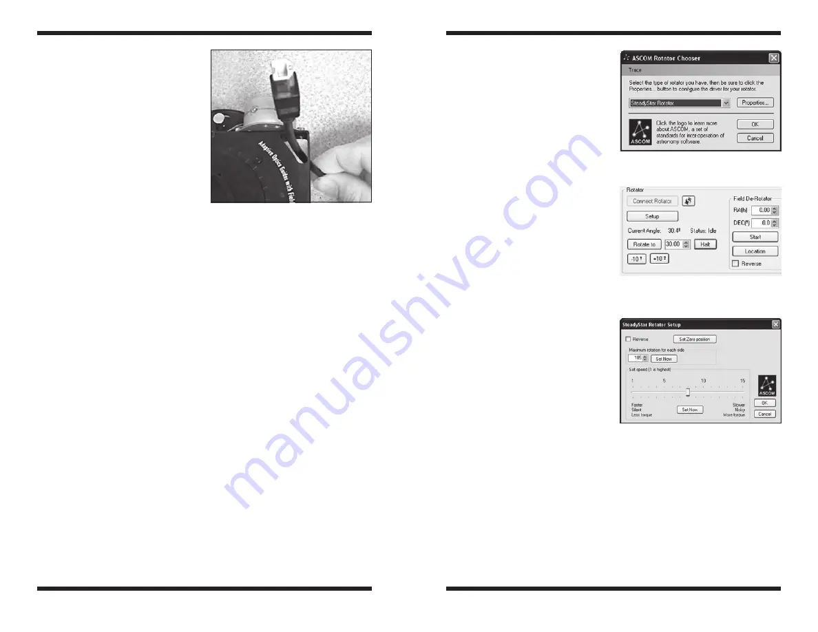
Figure 1.
The provided loop will fit some
cables to avoid problems from rotating your
imaging setup.
Figure 2.
The ASCOM Rotator Chooser
window
Figure 3.
The Rotator status section
allows you to jog the rotator to a custom
angle to find a guide star.
Figure 4.
The SteadyStar Rotator Setup
window


