4
During assembly (and anytime, for that matter), DO NOT
touch any of the lenses of the telescope, finder scope, or eye-
pieces, or the mirror of the diagonal, with your fingers. The
optical surfaces have delicate coatings on them that can eas-
ily be damaged if touched inappropriately. NEVER remove
any lens assembly from its housing for any reason, or the
product warranty and return policy are voided.
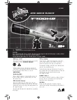
1. Screw a tripod leg lock thumbscrew into the hole in the
lower aluminum cuff on each tripod leg. Extend each leg
to the same length before tightening the thumbscrews.You
can readjust the legs to a more desirable height later, after
the scope is completely assembled.
2. Attach the three tripod legs to the base of the yoke mount
by lining up the holes in the top of the legs with the holes
in the base of the mount, then insert a tripod leg attach-
ment bolt through. The hinged accessory tray bracket on
each leg should be facing inward. Tighten the wing nuts on
the tripod leg attachment bolts finger-tight.
3. Stand the tripod upright with the yoke mount attached, and
spread the legs apart enough to attach the accessory tray
to the three hinged brackets on the legs. The brackets
should be positioned underneath the tray. Use the acces-
sory tray attachment screws and wing nuts to fasten the
accessory tray to the legs. Do not tighten the wing nuts yet.
4. Now, with the accessory tray attached but not tightened,
spread the tripod legs apart as far as they will go, until the
accessory tray brackets are taut. Then tighten the wing
nuts of the accessory tray attachment screws.
5. Next, tighten the wing nuts of the tripod leg attachment
bolts at the base of the yoke mount.
6. Attach the altitude micro-motion control rod to the optical
tube by first removing the screw from the micro-motion rod
attachment post on the side of the optical tube. Slide the
screw through the hole at the end of the micro-motion rod
and rethread the screw into the attachment post. Make
sure the screw is securely tightened.
7. To install the optical tube in the yoke mount, slide the alti-
tude micro-motion rod into its receptacle on the side of the
yoke. Make sure the altitude lock knob is sufficiently loose
to allow the rod to pass through the receptacle. Then set
the optical tube in the yoke, lining up the threaded holes
in the sides of the tube with the mounting holes in the
yoke. Thread in the yoke knobs until the telescope is held
securely. Retighten the altitude lock knob.
8. Insert the star diagonal into the focuser drawtube, secur-
ing it with the thumbscrews on the focuser drawtube.
9. Then insert an eyepiece into the star diagonal and secure
it in place with the thumbscrews on the diagonal. (Always
loosen the thumbscrews before rotating or removing the
diagonal or an eyepiece.)
10. Attach the finder scope bracket to the optical tube over the
two pre-installed bolts located near the focuser. It doesn’t
matter whether the bracket stem slants forward or back-
ward; choose whichever orientation you like. Secure the
bracket in place with the two round thumbscrews. Do not
loosen the two small hex nuts at the base of the bolts, as
they keep them from falling into the optical tube.
11. Lastly, install the finder scope in the bracket.To do this, we rec-
ommend first loosening the three finder scope alignment
screws so that the finder scope can be inserted through the
rings—eyepiece end first—without resistance. The larger,
objective lens of the finder scope should point in the same
direction as the objective lens of the main telescope. Then
lightly tighten the three alignment screws until the finder scope
is held securely in place and is roughly centered in the ring.
3. Aligning the Finder Scope
Using a low-power finder scope, with its wide field of view,
makes it easy to locate objects for observing through the main
telescope, which has a much narrower field of view. However,
the finder scope and the telescope need to be aligned so that
they both point to exactly the same spot in the sky.
1. Alignment is easiest to do in daylight hours. First, loosen the
azimuth and altitude lock knobs and the two yoke knobs so the
telescope can be moved freely. Then insert the lowest-power
eyepiece (longest focal length) into the star diagonal.
2. Point the main telescope at a discrete object such as the
top of a telephone pole or street sign that is at least quar-
ter-mile away. Move the telescope so the target object
appears in the very center of the field of view, when you
look into the eyepiece. Now tighten the altitude lock knob
(remember, just “finger tight” so you don’t strip the threads),
and lightly tighten the azimuth and yoke knobs (so slight
movement is still possible with light pressure on the tele-
scope tube). Use the altitude micro-motion control
thumbwheel and slight sideways pressure on the main tel-
escope tube to re-center the object in the field of view, if it
moved off center when you tightened the lock knobs.
3. Now look through the finder scope. Is the object centered in
the finder scope’s field of view, i.e., on the crosshairs? If not,
hopefully it will be visible somewhere in the field of view, so
that only fine adjustment of the three alignment screws will be
needed to center it on the crosshairs. If the object isn’t in the
field of view at all, you’ll have to make coarser adjustments to
the alignment screws to redirect the aim of the finder scope.
4. By loosening one alignment screw and tightening another,
you change the line of sight of the finder scope. Once the
target object is centered on the crosshairs of the finder
scope, look again in the main telescope’s eyepiece and
see if it is still centered there as well. If it isn’t, repeat the
entire process, making sure not to move the main tele-
scope while adjusting the alignment of the finder scope.
5. Check the alignment by pointing the main telescope at
another object and centering it in the finder scope. Then
look through the main telescope eyepiece and see if the
object is centered. If it is, your job is done. If it isn’t, make
the necessary adjustments to the finder scope’s alignment
screws until the object is centered in both instruments.
6. Finder scopes often come out of alignment during transport
of the telescope, so check it before each observing session.


