background image

IAP-420/420+  User  Manual 


ORing Industrial Networking Corp.                                                                                                47 
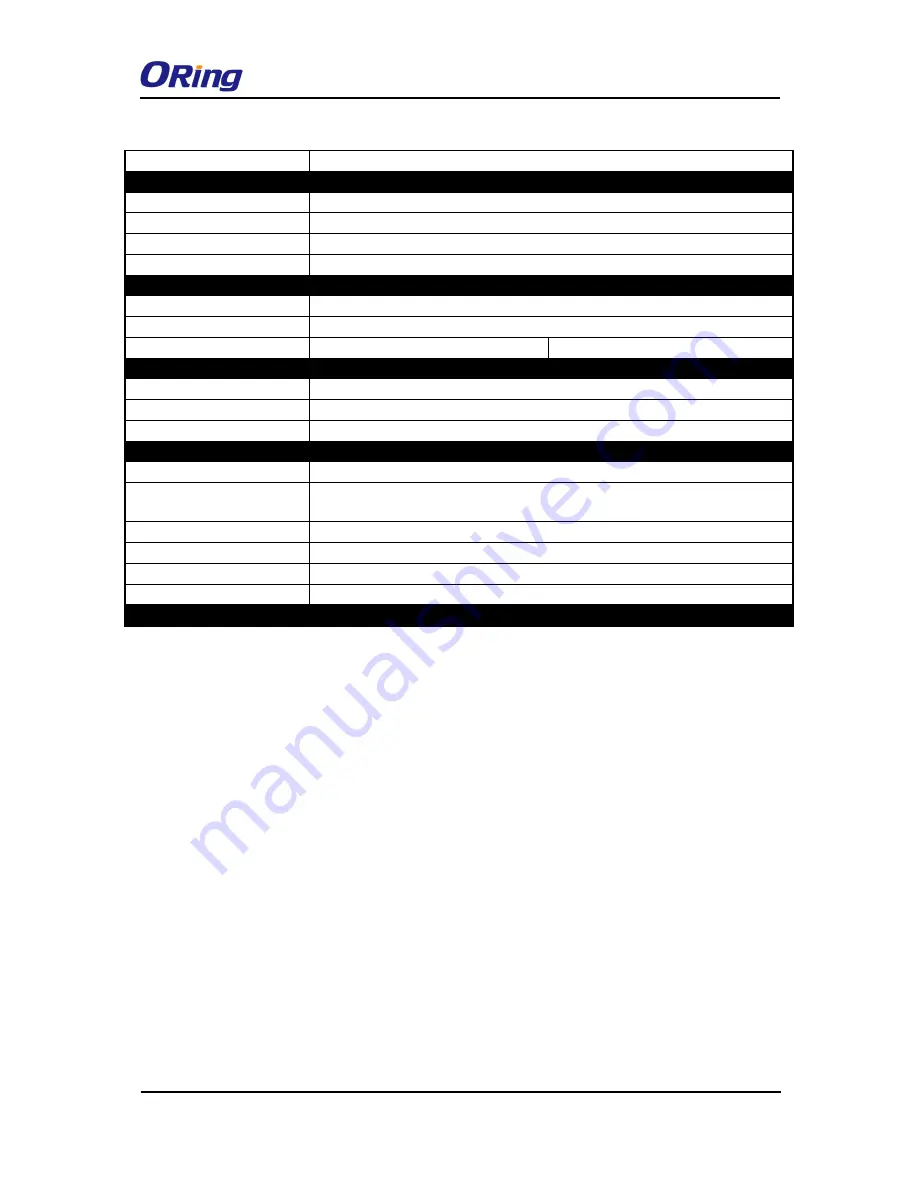
WLAN LEDs 

WLAN Link /ACT: Green: Blinking 

Power 


Redundant Input power 

Dual DC inputs.    12~48VDC on 4-pin terminal block 

Power consumption (Typ.) 

4watts 

Overload current protection 

Present 

Reverse polarity protection 

Present 

Physical Characteristic 


Enclosure


IP-30 

Dimension (W x D x H) 

41(W)x81(D)x95(H) mm   

Weight (g) 

292 

297 

Environmental 


Storage Temperature 

-40 to 85

o

C (-40 to 185

o

F) 

Operating Temperature 

-10 to 60

o

C (14 to 140

o

F) 

Operating Humidity 

5% to 95% Non-condensing 

Regulatory approvals 


EMI 

FCC Part 15, CISPR (EN55022) class A 

EMS 

EN61000-4-2  (ESD),  EN61000-4-3  (RS),  EN61000-4-4  (EFT),  EN61000-4-5 
(Surge), EN61000-4-6 (CS), EN61000-4-8, EN61000-4-11 

Shock 

IEC60068-2-27 

Free Fall 

IEC60068-2-32 

Vibration 

IEC60068-2-6 

Safety 

EN60950-1 

Warranty 

3 years 

Содержание IAP-420 Series

Страница 1: ...al l I IE EE EE E 8 80 02 2 1 11 1 b b g g n n W Wi ir re el le es ss s A Ac cc ce es ss s P Po oi in nt t U Us se er r M Ma an nu ua al l V Ve er rs si io on n 1 1 1 1 S Se ep pt te em mb be er r 2 20 01 14 4 w ww ww w o or ri in ng g n ne et tw wo or rk ki in ng g c co om m ...

Страница 2: ...nses apportioned by ORing and the distributor This warranty does not cover product modifications or repairs done by persons other than ORing approved personnel and this warranty does not apply to ORing products that are misused abused improperly installed or damaged by accidents Please refer to the Technical Specifications section for the actual warranty period s of the product s associated with t...

Страница 3: ...lation 7 3 2 Wall Mounting 8 3 3 Wiring 9 3 3 1 Grounding 9 3 3 2 Dual Power Inputs 9 4 1 Ethernet Cables 11 4 2 RJ 45 Pin Assignment 11 4 3 Wireless Antenna 11 Management 13 5 1 Open Vision Configuration 13 5 2 UPnP Equipment 13 5 3 Web Browser Management 15 5 4 Configuration 16 5 4 1 Overview 16 System Info 16 LAN Info 17 Wireless Info 17 5 4 2 Basic Setting 17 System Info Settings 17 LAN Settin...

Страница 4: ...arning Settings 37 System Log 37 E mail 38 SNMP 40 5 4 6 System Status 41 Wireless Link List 41 DHCP Client List 41 Traffic Port Status 41 System Log 42 5 4 7 Administrator 42 Password 42 Configuration 43 Firmware Upgrade 43 Load Factory Default 44 Restart 44 Technical Specifications 46 Compliance 48 ...

Страница 5: ...peed air connectivity WLAN interface supports up to 150 Mbps Provides high security via WEP WPA WPA PSK TKIP AES WPA2 WPA2 PSK TKIP AES 802 1X authentication Supports X Roaming 100 ms Supports AP client bridge AP client modes Dual redundant Ethernet ports Recovery time 10ms Secured management by HTTPs Wireless connection status monitoring Event warning by Syslog e mail SNMP trap relay and beeper 1...

Страница 6: ...on the front panel Port Description 10 100Base T X Fast Ethernet Ports 10 100Base T X RJ 45 fast Ethernet ports supporting auto negotiation Default setting including Speed auto Duplex auto The ETH1 port of IAP 420 is PoE enabled ANT 1 x reversed SMA connector for Wi Fi antennal Note For PoE Ethernet switch options please refer to information on the ORing IPS series IAP 420 IAP 420 ...

Страница 7: ...ated 2 3 Rear Panel On the rear panel of the device sit three sets of screw holes The two sets placed in triangular patterns on both ends of the rear panel are used for wall mounting red boxes in the figure below and the set of four holes in the middle are used for Din rail installation blue box in the figure below For more information on installation please refer to 3 1 Din rail Installation 1 Po...

Страница 8: ...IAP 420 420 User Manual ORing Industrial Networking Corp 6 2 4 Top Panel 1 Terminal block 2 Wall mount screw holes ...

Страница 9: ...N rail kit to allow you to fasten it to a DIN rail in any environments DIN rail Kit Measurement Unit mm Step 1 Slant the device and screw the Din rail kit onto the back of the device right in the middle of the back panel Step 2 Slide the device onto a DIN rail from the Din rail kit and make sure the device clicks into the rail firmly ...

Страница 10: ...he wall follow the steps Step 1 Screw the two pieces of wall mount kits onto both ends of the rear panel of the device A total of six screws are required as shown below Step 2 Use the device with wall mount plates attached as a guide to mark the correct locations of the four screws Step 3 Insert four screw heads through the large parts of the keyhole shaped apertures and then slide the device down...

Страница 11: ...1 Grounding Grounding and wire routing help limit the effects of noise due to electromagnetic interference EMI Run the ground connection from the ground screw to the grounding surface prior to connecting devices 3 3 2 Dual Power Inputs The device has two sets of power inputs power input 1 and power input 2 on a 4 pin terminal block connector on the top panel Follow the steps below to wire redundan...

Страница 12: ...ious damage to your equipment 4 Use separate paths to route wiring for power and devices If power wiring and device wiring paths must cross make sure the wires are perpendicular at the intersection point 5 Do not run signal or communications wiring and power wiring through the same wire conduit To avoid interference wires with different signal characteristics should be routed separately 6 You can ...

Страница 13: ...gnment With 10 100Base T X cables pins 1 and 2 are used for transmitting data and pins 3 and 6 are used for receiving data 10 100 Base T X RJ 45 Pin Assignments The device also supports auto MDI MDI X operation You can use a straight through cable to connect PC and the device The following table below shows the 10 100BASE T X MDI and MDI X port pin outs 4 3 Wireless Antenna The device uses one rev...

Страница 14: ...IAP 420 420 User Manual ORing Industrial Networking Corp 12 ...

Страница 15: ...ep 2 Choose your access point The functions of the AP will be shown in a tree structure Step 3 Type in the username and password to log in to setup the AP 5 2 UPnP Equipment The device supports UPnP therefore when you connect the device to the PC it will discover the presence of the device automatically To check the connection of the device to you PC follow the steps below Step 1 Go to Control Pan...

Страница 16: ... computer you will find an UPnP icon of the device Step 3 Click on the icon and you will find the UPnP device in My Network Places Step 4 Right click the UPnP device and choose Properties the following picture will be shown Step 5 Double click the device icon will lead you to the management web page ...

Страница 17: ...w Java Applets to open sockets You need to explicitly modify browser settings in order to enable Java Applets to use network ports Open a web browser on your computer and type http 192 168 10 2 default gateway IP of the device in the address box to access the webpage A login window will pop up where you can enter the default login name admin and password admin For security reasons we strongly reco...

Страница 18: ...d encryption On top of the Home screen shows information about the firmware version and uptime Label Description Firmware Shows the current firmware version Uptime Shows the elapsed time since the AP is started 5 4 1 Overview System Info This page will show the basic information of the device based on the settings you input in Basic Settings System Info Settings The information includes model name...

Страница 19: ...es including MAC address IP address subnet mask and gateway Wireless Info This page will show the wireless information of the device based on the settings you input in Wireless Settings The information includes MAC address SSID peer AP SSID encryption type channel number operation mode and RF type 5 4 2 Basic Setting System Info Settings This section allows you to input the basic information for t...

Страница 20: ...ere the device is located Device Description Enter a description for the device LAN Setting This page allows you to configure the IP settings of the LAN port for the device To access the AP normally a valid IP address of your LAN should be designated to the LAN interface The default IP setting is DHCP server which will obtain an IP address automatically ...

Страница 21: ...the default value All devices on the network must have the same subnet mask to communicate on the network Default Gateway Enter the IP address of the device in your network Obtain DNS server address automatically Obtains a DNS server address from a DHCP server If you have chosen to obtain an IP address automatically this option will be selected accordingly Use the following DNS server addresses Sp...

Страница 22: ...nd time will help the system log events You can set up a NTP Network Time Protocol client to synchronize date time to a NTP server on the Internet Label Description NTP Enables or disables NTP function NTP Server 1 The primary NTP server Time Zone Select the time zone you are located in Synchronize Specify the scheduled time for synchronization Local Date Set a local date manually Local Time Set a...

Страница 23: ... AP will act as a central connection point which other wireless clients can connect to AP Client This mode provides a one to many MAC address mapping mechanism such that multiple stations behind the AP can transparently connect to the other AP even if they don t support WDS Client In this mode the AP functions as a wireless client to connect your wired devices to a wireless network This mode provi...

Страница 24: ...e the default value Channel Specify a channel to be used Channel 6 is the default channel You can also select a new number from the dropdown list All devices on the network must be set to the same channel to communicate on the network Wireless channel must be the same as the other device in the group Security Options You can choose the security type for your WLAN connection from the following opti...

Страница 25: ...ation server on the network 802 1x Authentication through RADIUS server When you set security type as WEP the following fields will appear to allow you to configure individual settings Label Description Auth Mode Available values include Open Shared and WEPAUTO When choosing Open or Shared all of the clients must select the same authentication to associate this AP If select WEPAUTO the clients do ...

Страница 26: ...configure individual settings Label Description Auth Mode Available values include WPAPSK WPA2PSK and WPAPSK WPA2PSK mix WPAPSK and WPA2PSK will encrypt the link without additional RADIUS server only an access point and client station that supports WPA PSK is required For WPA WPA2 authentication is achieved via WPA RADIUS Server You need a RADIUS or other authentication server on the network Encry...

Страница 27: ...achieved via WPA RADIUS Server You need a RADIUS or other authentication server on the network Encryption Type Available values include TKIP AES and TKIP AES mix WPA PSK uses TKIP encryption and WPA2 PSK uses AES encryption TKIP AES provides the most reliable security and is easiest to implement Radius Server IP Enter the IP address of the RADIUS server Radius Port Enter the RADIUS port default is...

Страница 28: ...active key Key 1 to 4 Input up to four encryption keys Radius Server IP Enter the IP address of the RADIUS server Radius Port Enter the RADIUS port default is 1812 Shared Secret Enter the RADIUS password or key RADIUS Remote Authentication Dial In User Service is a widely deployed protocol that enables companies to authenticate and authorize remote users access to a system or service from a centra...

Страница 29: ...ot authorized the RADIUS server sends a reject message back to the remote access server and the connection attempt is rejected The principle of the Radius server is shown in the following pictures AP Client Mode This mode provides a one to many MAC address mapping mechanism such that multiple stations behind the AP can transparently connect to the other AP even if they don t support WDS ...

Страница 30: ...security type for your WLAN connection from the following options None no encryption WEP WEP Wired Equivalent Privacy is a wireless security protocol for WLAN WEP will encrypt data transmitted on the WLAN WPA WPA2 Personal uses a pre shared key for authentication This pre shared key is then dynamically sent between the AP and clients Each authorized computer is given the same pass phrase Peer AP S...

Страница 31: ...cription Peer AP SSID Enter the SSID of the AP you want to connect as a client Peer AP BSSID Enter the BSSID Wireless MAC address to limit client target Site Scan Enables or disables slave mode Security Type Select the security type used by the client you want to connect ...

Страница 32: ...les slave mode Channel Choose a fixed channel from the drop down list Security Type Select the security type used by the client you want to connect Note the channel and the security settings security type password should be identical on the two access points Set WDS as Bridge Mode In the mode the AP acts as a standard bridge that forwards traffic between WDS links links connected to other AP wirel...

Страница 33: ...own all DHCP server functions of the AP 3 Enable WDS 4 Each AP should have the same setting except Peer Mac Address should be set to the other s Mac address 5 The settings of security and channel must be the same 6 The distance of the AP should be limited within a certainty area Set WDS as Repeater Mode In this mode repeater is used to extend the range of the wireless infrastructure by forwarding ...

Страница 34: ...IAP 420 420 User Manual ORing Industrial Networking Corp 32 ...

Страница 35: ...reless devices The beacon interval value indicates the frequency interval of the beacon Increasing the beacon interval reduces the number of beacons and the overhead associated with them The default value is 100 but 50 is recommended when reception is poor DTIM Interval The default value is 1 This value between 1 and 255 milliseconds indicates the interval of the Delivery Traffic ...

Страница 36: ...is the amount of time a wireless device attempting to send will wait for a recipient to acknowledge that it is ready Normally the AP sends a RTS frame to a station and negotiates the sending of data After receiving the RTS the station responds with a CTS Clear to Send frame to acknowledge the right to begin transmission To ensure communication the maximum value should be used which is the default ...

Страница 37: ...adcast When wireless clients survey the local area for wireless networks to associate with they will detect the SSID broadcasted by the AP Click Enable if you want to broadcast the AP SSID otherwise click Disable to inactivate the function X Roaming Disable Disable X Roaming protocol Standard Roaming group does not require the same wireless channel but the speed is slower than using the fixed chan...

Страница 38: ... Enabled or Disabled to activate or deactivate MAC filters Options Select one of the options to allow or deny the MAC address in the list Associated Clients Shows the wireless MAC addresses associated with the device MAC Filter Table You can edit up to MAC addresses in these fields Misc Settings ...

Страница 39: ...LLDP protocol 5 4 5 Event Warning Settings System Log When an error occurs the device will notify you through system log e mail SNMP and relay You can choose the system to issue a notification when specific events occur by checking the box next to the event This page shows the recorded events and setting changes of the AP Rebooting the device will clear the list ...

Страница 40: ...Corp 38 Label Description Syslog Server IP Enter the IP address of a remote server if you want the logs to be stored remotely Leave it blank will disable remote syslog Syslog Server Port Specifies the port to be logged remotely Default port is 514 E mail ...

Страница 41: ...Corp 39 Label Description SMTP Server Enter a backup host to be used when the primary host is unavailable Server Port Specifies the port where MTA can be contacted via SMTP server E mail Address 1 4 Enter the mail address that will receive notifications ...

Страница 42: ...IAP 420 420 User Manual ORing Industrial Networking Corp 40 SNMP Label Description SNMP Agent SNMP Simple Network Management Protocol Agent is a service ...

Страница 43: ... is used for read write community SysLocation Specifies sysLocation string SysContact Specifies sysContact string 5 4 6 System Status Wireless Link List This page displays the information of the wireless clients connected to the device including their MAC address data rate and link types DHCP Client List This page lists the devices on your network that are receiving dynamic IP addresses from the d...

Страница 44: ...ies in System Log and provide the file for you to review You can click Refresh to renew the page or Clear to clear all or certain log entries 5 4 7 Administrator Password This page allows you to change the username and password You must type in the new password twice to confirm the default username and password are admin ...

Страница 45: ...red in the local hard drive Upload You can restore configurations to previous status by installing a previous configuration file To do this click on Browse to locate the file you want to upload in the local hard drive and click Upload Restore Default Settings Click to reset the device to the factory settings The device will reboot to validate the default settings Firmware Upgrade ORing launches ne...

Страница 46: ...e the firmware After upgrade completes successfully reboot the device During firmware upgrading do not turn off the power of the device or press the reset button Load Factory Default You can use this page to restore the device to factory default settings Make sure to save the device settings before clicking on this button All current settings will be lost after you click this button Restart Click ...

Страница 47: ...IAP 420 420 User Manual ORing Industrial Networking Corp 45 ...

Страница 48: ...CE ETSI 2 412 2 472 GHz 13 channels Transmission Rate 802 11b 1 2 5 5 11 Mbps 802 11g 6 9 12 18 24 36 48 54 Mbps 802 11n 40MHz UP to 150 Mbps Transmit Power 802 11b 13 5dBm 1 5dBm 802 11g 13 5dBm 1 5dBm 802 11n 2 4G 20MHz 13 5dBm 1 5dBm 802 11n 2 4G 40MHz 13 5dBm 1 5dBm Receiver Sensitivity 802 11b 90dBm 2dBm 1Mbps 802 11g 72dBm 2dBm 54Mbps 802 11n 2 4G 40MHz MCS7 68dBm 2dBm Encryption Security WE...

Страница 49: ...istic Enclosure IP 30 Dimension W x D x H 41 W x81 D x95 H mm Weight g 292 297 Environmental Storage Temperature 40 to 85o C 40 to 185o F Operating Temperature 10 to 60o C 14 to 140o F Operating Humidity 5 to 95 Non condensing Regulatory approvals EMI FCC Part 15 CISPR EN55022 class A EMS EN61000 4 2 ESD EN61000 4 3 RS EN61000 4 4 EFT EN61000 4 5 Surge EN61000 4 6 CS EN61000 4 8 EN61000 4 11 Shock...

Страница 50: ...atement This device complies with Industry Canada licence exempt RSS standard s Operation is subject to the following two conditions 1 this device may not cause interference and 2 this device must accept any interference including interference that may cause undesired operation of the device Le présent appareil est conforme aux CNR d Industrie Canada applicables aux appareils radio exempts de lice...

Страница 51: ...iated power e i r p is not more than that permitted for successful communication Afin de réduire les interférences radio potentielles pour les autres utilisateurs le type d antenne et son gain doivent être choisie que la puissance isotrope rayonnée équivalente PIRE est pas plus que celle premise pour une communication réussie RF exposure warning The equipment complies with RF exposure limits set f...

Отзывы: