


Professional Collection Manual
4
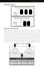
70V/100V System
70/100-Volt systems are advantageous when the design calls for multiple speakers from the same
amplifier and/or long-distance wire runs. The Origin Acoustics 70V/100V loudspeakers feature
multiple taps off the transformer adjusted by a rotary switch at the front side of the speaker.. The
higher the wattage selected the more output will be generated by the speaker. Please note, 70V
is common in the U.S. while 100V is the common voltage internationally, especially in Europe. A
simple calculation is used to determine how many speakers can be driven on a single amplifier
channel. First, for safety purposes, it is recommended to make the calculations based on 80%
of the amplifiers rated power. For example, a 500-watt amplifier would safely deliver 400 watts
of usable power (500 x 0.8 = 400). Now it is simply a matter of dividing 400 by the tap setting of
the speakers. For example, if the speakers are set at a 15W tap, the amplifier would be capable of
driving 26 speakers per channel. At a 30W tap that would be 13 speakers. At a 60W tap that would
be 6 speakers and so on.
As you can see, if you need coverage over a wide area and it requires numerous speakers, a
70V/100V system presents a tremendous advantage. However, it should be noted that the higher
the wattage tap the higher the fidelity and the greater SPL that can be delivered from each
speaker. Therefore, it is best to determine the total number of speakers needed and set the taps
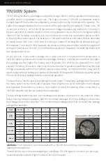
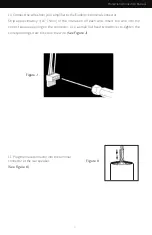
as high as possible within the amplifier’s power output rating. As mentioned, the rotary switch
used to adjust the tap setting is located at the front side of the speaker. It is best to leave the grilles
off until all of the tap settings have been properly adjusted.
The table below lists the power tap settings for each model. These same settings are reflected on
the rotary switch on the front side of speaker. Note that there is an 8Ω setting for both voltages
that bypasses the transformer entirely. Use caution to avoid this setting when connected to a
70V/100V amplifier as this can destroy the loudspeaker.
The tap setting determines how much wattage each speaker will draw from the amplifier. When
daisy-chaining multiple speakers, add the combined wattages of all tap settings to determine
the wattage draw on the amplifier. The combined total wattage should never exceed the wattage
rating of the amplifier.
WARNING:
The 8 Ω position cannot be used with a 70/100V connection as it will damage or
destroy the transformer.
Should you be uncomfortable designing or installing a 70/100V system, or should you have any
questions please contact Origin Acoustics Technical Support.
Model
PP80
PP60
PP50
PPSUB8
PBR68
Position
1
2
3
4
5
70V
-
60W
30W
15W
7.5W
100V
-
-
60W
30W
15W
8ohm
8 Ω
-
-
-
-
70V
-
30W
15W
7.5W
3.75W
100V
-
-
30W
15W
7.5W
8ohm
8 Ω
-
-
-
-
70V
-
120W
60W
30W
15W
100V
-
-
120W
60W
30W
8ohm
8 Ω
-
-
-
-
70V
-
60W
30W
15W
7.5W
100V
-
-
60W
30W
15W
8ohm
8 Ω
-
-
-
-
Tap Switch for PP60 & PP80
Содержание PP50B
Страница 13: ...Professional Collection Manual NOTES ...


