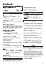

4
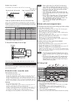
ContactycapacityyofySW1
Single-phase 100 − 115 V: 125 VAC 5 A or more (Inductive load)
Single-phase 200 − 230 V: 250 VAC 5 A or more (Inductive load)
z
K
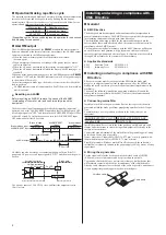
Ⅱ
series,
V
series,World
K
series
Inductionmotor/Reversiblemotor
9
ALARM output
2
1
11
6
8
4
7
1
11
U1
U2
5
CCW operation input
+24 V
CW operation input
Black
Brake pack
terminal No.
Red
White
Capacitor
Capacitor
GND
Brake release input
2
ON
ON
24 VDC
0.1 A or more
+
-
Z2
L
AC power supply
∗
N
L
AC power supply
∗
N
∗
Single-phase 100 V/110 V/115 V, Single-phase 200 V/220 V/230 V
FG
ON
ON
Motor
Motor
Terminal box type
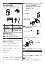
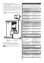
z
Motorwithelectromagneticbrake
9
ALARM output
∗
Single-phase 100 V/110 V/115 V, Single-phase 200 V/220 V/230 V
+24 V
CW operation input
CCW operation input
GND
Brake release input
Red
∗
1
White
Black
Capacitor
Orange
∗
2
Orange
∗
2
2
10
1
11
6
8
4
7
5
24 VDC
0.1 A or more
+
-
Brake pack
terminal No.
L
AC power supply
∗
N
∗
1 For 6 to 40 W type of
K
series motors, the color
of lead wire is gray, and that of 60 W and 90 W
type is yellow.
∗
2 For 6 to 40 W type of
K
series motors, the color
of lead wire is yellow.
ON
ON
FG
Motor
Terminalyboxytype
Capacitor
Motor
9
ALARM output
∗
Single-phase 100 V/110 V/115 V, Single-phase 200 V/220 V/230 V
+24 V
CW operation input
CCW operation input
GND
Brake release input
6
8
4
7
5
24 VDC
0.1 A or more
+
-
FG
Brake pack
terminal No.
AC power supply
∗
ON
ON
2
10
1
11
L
N
U1
U2
Z2
MB
MB
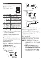
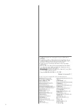
z
FPW
seriesInductionmotor
2
1
11
Black
Red
White
Green/Yellow
Capacitor
L
AC power supply
∗
N
Brake pack
terminal No.
9
ALARM output
∗
Single-phase 100 V/110 V/115 V, Single-phase 200 V/220 V/230 V
+24 V
CW operation input
CCW operation input
GND
Brake release input
6
8
4
7
5
24 VDC
0.1 A or more
+
-
ON
ON
FG
Motor
z
K
seriesInductionmotor
CCW operation input is not used.
The connection of the 5 W motor of the terminal box type is the same as that
of the
K
series reversible motor.
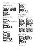
Clockwiseoperation
Counterclockwiseoperation
2
1
11
6
8
7
+24 V
CW operation input
Black
Blue
Yellow
White
Capacitor
GND
Brake release input
4
24 VDC
0.1 A or more
+
-
∗
Single-phase 100 V, Single-phase 200 V
L
AC power supply
∗
N
Brake pack
terminal No.
ON
ON
FG
Motor
2
1
11
6
8
7
+24 V
CW operation input
White
Blue
Yellow
Black
Capacitor
GND
Brake release input
4
24 VDC
0.1 A or more
+
-
∗
Single-phase 100 V, Single-phase 200 V
L
AC power supply
∗
N
Brake pack
terminal No.
ON
ON
FG
Motor
1
11
4
3
Capacitor
2
∗
Single-phase 100 V, Single-phase 200 V
2
L
AC power supply
∗
N
1
ON
ON
Motor
Terminal box type
1
11
1
3
Capacitor
2
∗
Single-phase 100 V, Single-phase 200 V
2
L
AC power supply
∗
N
4
ON
ON
Terminal box type
Motor
z
K
seriesReversiblemotor
2
1
11
6
8
4
7
1
11
3
2
5
CCW operation input
+24 V
CW operation input
Black (Red)
Brake pack
terminal No.
Yellow (Gray)
White (Blue)
Capacitor
Capacitor
GND
Brake release input
2
∗
Single-phase 100 V, Single-phase 200 V
24 VDC
0.1 A or more
+
-
1
L
AC power supply
∗
N
L
N
Colors in parentheses ( ) are for the lead
wires of the reversible-type 1 W motor
(Single-phase 100 V/110 V/115 V type).
ON
ON
ON
ON
FG
Motor
AC power supply
∗
Terminal box type
Motor