3
Secure the lead wires at the connection part to prevent the connection
part from receiving stress due to the flexing of the lead wires or the lead
wires’ own mass. Also, do not excessively bend the lead wires near the
connection part of the connector. Applying stress on the motor lead wires
may cause poor contact or disconnection, leading to malfunction or heat
generation.
Bend excessively
Have length allowances
More than 4 times
of the diameter of
the lead wires.
Connection with the drivers of Oriental Motor
Refer to the following table when connecting with the drivers of Oriental Motor.
“Color” in the table shows the colors of lead wires of the connection cable (accessory).
•
Connection with the
CVD
driver
Driver
CN2 Pin No.
Connector type
Lead wire type
Pin No.
Color
Color
1
4
Blue
Blue
2
5
Red
Red
3
−
−
4
2
Green
Green
5
1
Black
Black
Installation
Location for installation
The motor is designed and manufactured to be incorporated in equipment. Install it in a
well-ventilated location that provides easy access for inspection.
The location must also satisfy the following conditions:
y
Inside an enclosure that is installed indoors (provide vent holes)
y
Operating ambient temperature
−10 to +50 °C (+14 to +122 °F) (non-freezing)
Harmonic geared type: 0 to +40 °C (+32 to +104 °F) (non-freezing)
y
Operating ambient humidity 85% or less (non-condensing)
y
Area that is free of explosive atmosphere or toxic gas (such as sulfuric gas) or liquid
y
Area not exposed to direct sun
y
Area free of excessive amount of dust, iron particles or the like
y
Area not subject to splashing water (rain, water droplets), oil (oil droplets) or other
liquids
y
Area free of excessive salt
y
Area not subject to continuous vibration or excessive shocks
y
Area free of excessive electromagnetic noise (from welders, power machinery, etc.)
y
Area free of radioactive materials, magnetic fields or vacuum
y
1,000 m (3,300 ft.) or lower above sea level
Installation method
The motor can be installed in any direction.
Install the motor onto an appropriate flat metal plate having excellent vibration
resistance and heat conductivity.
When installing the motor, secure it with bolts (not supplied) so that there is no gap
between the motor and metal plate.
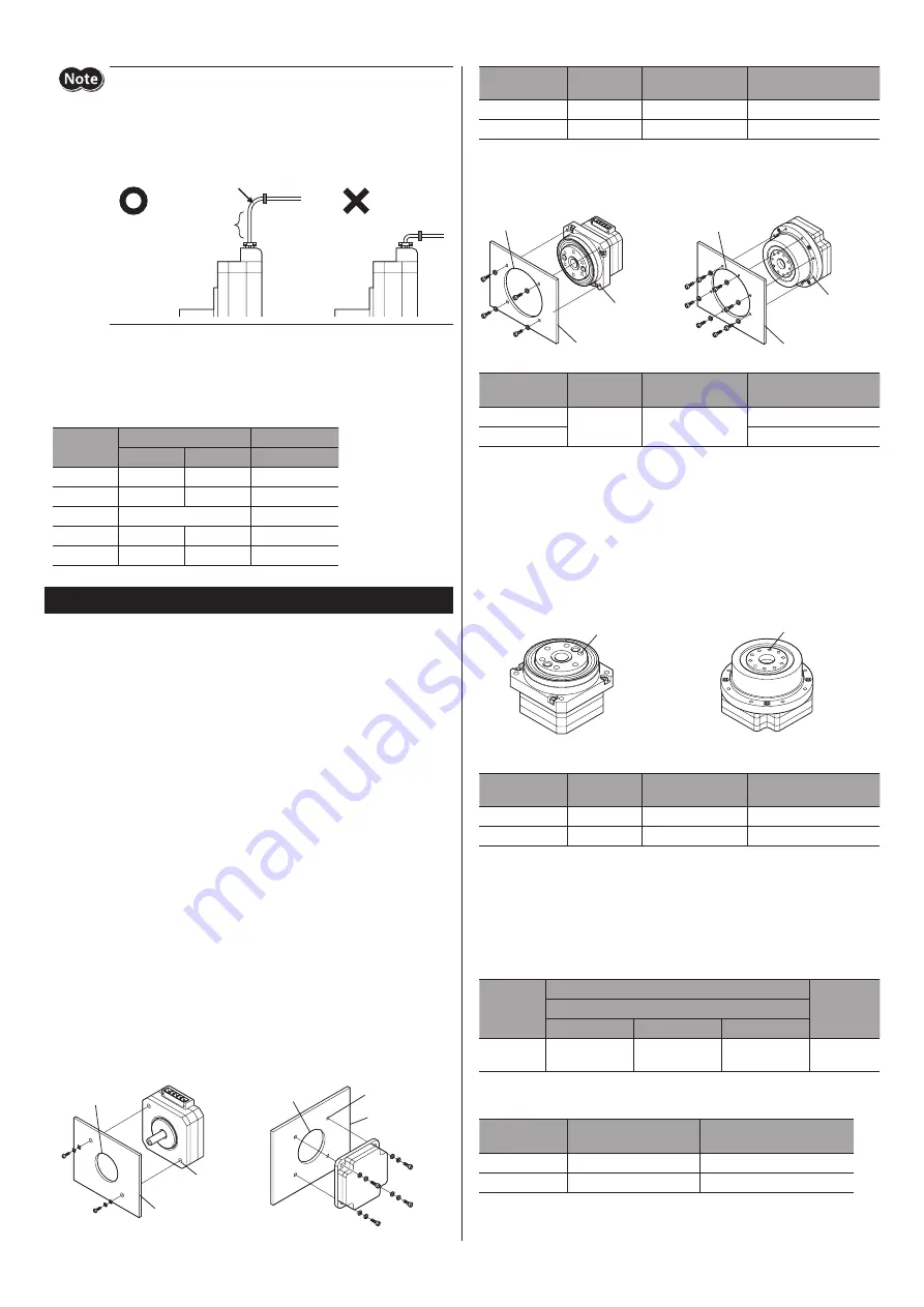
z
Standard type
Metal plate
Mounting holes
Pilot holder
Metal plate
Mounting
holes
Motor frame size
42 mm (1.65 in.)
Motor frame size
60 mm (2.36 in.)
Pilot holder
Motor frame size
[mm (in.)]
Nominal size
Tightening torque
[N·m (oz-in)]
Effective depth of screw
thread [mm (in.)]
42 (1.65)
M3
1 (142)
4.5 (0.18)
60 (2.36)
M4
2 (280)
−
z
Harmonic geared type
Pilot holder
Metal plate
Mounting
holes
Pilot holder
Metal plate
Mounting
holes
Motor frame size
51 mm (2.01 in.)
Motor frame size ø72 mm (2.83 in.)
Motor frame size
[mm (in.)]
Nominal size
Tightening torque
[N·m (oz-in)]
Effective depth of screw
thread [mm (in.)]
51 (2.01)
M3
1 (142)
7 (0.28)
ø72 (2.83)
5 (0.2)
Installing a load
When connecting a load to the motor, align the centers of the motor output shaft and
load shaft. Be careful not to damage the output shaft or bearings when installing a
coupling or pulley to the motor output shaft.
•
Harmonic geared type
Install a load using the load mounting holes.
Motor frame size
51 mm (2.01 in.)
Motor frame size ø72 mm (2.83 in.)
Load mounting
holes (6 places)
Load mounting
holes (10 places)
Load mounting hole
Motor frame size
[mm (in.)]
Nominal size
Tightening torque
[N·m (oz-in)]
Effective depth of screw
thread [mm (in.)]
51 (2.01)
M3
1 (142)
6 (0.24)
ø72 (2.83)
M3
1 (142)
7 (0.28)
Permissible radial load, permissible axial load and
permissible moment load
The radial load, axial load and moment load on the motor output shaft must be kept
under the permissible values in the table below.
z
Standard type
Motor frame
size
[mm (in.)]
Permissible radial load [N (lb.)]
Permissible
axial load
[N (lb.)]
Distance from the tip of motor output shaft [mm (in.)]
0 (0)
5 (0.2)
10 (0.39)
42 (1.65)
60 (2.36)
20 (4.5)
25 (5.6)
34 (7.6)
5 (1.12)
z
Harmonic geared type
Motor frame size
[mm (in.)]
Permissible axial load
[N (lb.)]
Permissible moment load
[N·m (oz-in)]
51 (2.01)
200 (45)
8.5 (1200)
ø72 (2.83)
450 (101)
5.0 (710)


