6
•
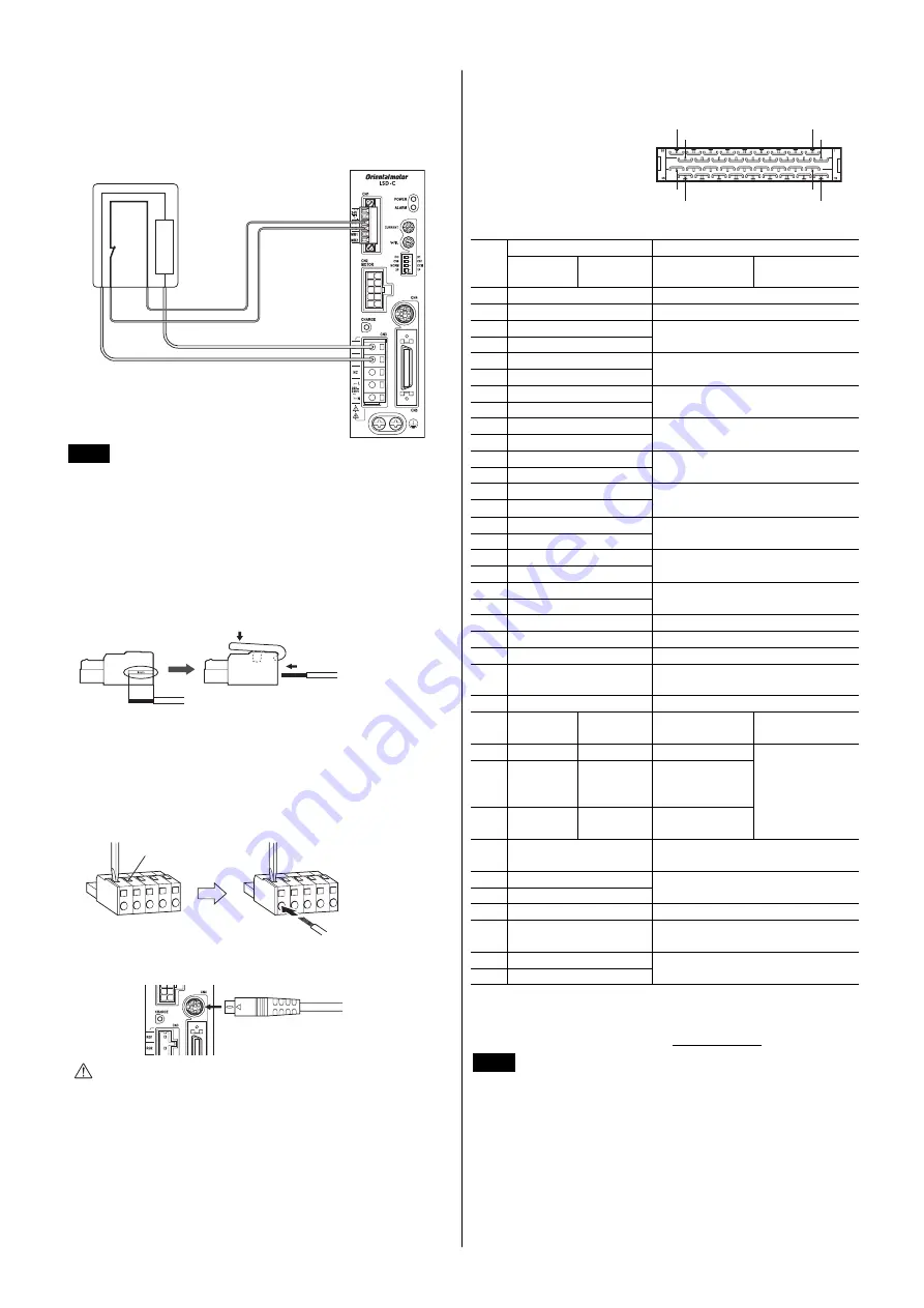
Connecting the regeneration unit
If vertical drive (gravitational operation) such as elevator
applications is performed or if sudden start-stop operation of a large
inertial load is repeated frequently, connect the regeneration unit
RGB100
.
AWG22
AWG18
R
䋺
150
Ω
To RG1 and RG2
terminals on CN3
To TH1 and TH2
terminals on CN1
Regeneration
unit
RGB100
150 °C (302 °F)
[N.C.]
Note
•
Before connecting the regeneration unit, be sure to
remove the jumper wire from the CN1 connector.
•
If the current consumption of the regeneration unit
exceeds the allowable level, the thermostat will be
triggered and a regeneration unit overheat alarm will
generate. If a regeneration unit overheat alarm
generates, turn off the power and check the content
of the error.
CN3
2. Push the connector wiring lever
in the direction of the arrow.
3. Insert the cable.
1. Strip off the cable sheath
based on the strip gauge.
You can also connect the power supply cable using a flat-tip
screwdriver.
Insert a flat-tip screwdriver with a tip of 3.0 to 3.5 mm (0.12 to 0.14
in.) in width into the insertion port and push. In this condition, insert
the cable.
Screwdriver insertion port
Insert the cable while
pushing down the screwdriver.
CN4
OPX-2A
㩷㪺㪸㪹㫃㪼㩷㫆㫉㩷㪺㫆㫄㫄㫌㫅㫀㪺㪸㫋㫀㫆㫅
㪺㪸㪹㫃㪼㩷㪽㫆㫉㩷㪻㪸㫋㪸㩷㫊㪼㫋㫋㫀㫅㪾㩷㫊㫆㪽㫋㫎㪸㫉㪼
Caution
The data edit connector (CN4) and I/O signals
connector (CN5) are not insulated. When
grounding the positive terminal of the power
supply, do not connect any equipment (PC, etc.)
whose negative terminal is grounded. Doing so
may cause the driver and these equipments to
short, damaging both.
CN5
Use a shielded cable for I/O signals.
Connector pin assignment
(viewed from soldering side)
1
2
17
18
19
20
35
36
•
Pin assignment
Operating mode
Name
Pin
No
Positioning
operation
Push-motion
operation
∗2
Positioning
operation
Push-motion
operation
∗2
1
−
−
2 GND
Ground
connection
3 ASG+
4 ASG
−
A-phase pulse output
(line driver)
5 BSG+
6 BSG
−
B-phase pulse output
(line driver)
7 TIM1+
8 TIM1
−
Timing output (line driver)
9 ALM+
10
ALM
−
Alarm output
11
WNG+
12
WNG
−
Warning output
13
END+
14
END
−
Positioning complete output
15
READY+/AL0+
∗1
16
READY
−
/AL0
−
∗1
Operation ready complete output/
Alarm code output 0
17
TLC+/AL1+
∗1
18
TLC
−
/AL1
−
∗1
Torque limit output/
Alarm code output 1
19
TIM2+/AL2+
∗1
20
TIM2
−
/AL2
−
∗1
Timing output (open collector)/
Alarm code output 2
21
GND Ground
connection
22
IN-COM Input
common
23
C-ON
Current on input
24
CLR/ALM-RST
Deviation clear input/
Alarm reset input
25
CCM
Current control mode ON input
26
CS
T-MODE
∗1∗2
Resolution
selection input
Push-motion
operation ON
27
−
M0
∗1∗2
−
28
RETURN
M1
∗1∗2
Return to
electrical home
operation
29
P-RESET
M2
∗1∗2
Position reset
input
Push-current
setting selection
input
30
FREE
Excitation OFF, electromagnetic
brake release
31
CW+/PLS+
32
CW
−
/PLS
−
CW pulse input/Pulse input
(+5 V or line driver)
33
CW+24 V/PLS+24 V
CW pulse input/Pulse input (+24 V)
34
CCW+24 V/DIR+24 V
CCW pulse input/Direction input
(+24 V)
35
CCW+/DIR+
36
CCW
−
/ DIR
−
CCW pulse input/Direction input
(+5 V or line driver)
∗1
The signal will become effective if the applicable setting has been
changed using the
OPX-2A
or
MEXE02
.
∗2
These signals are used to perform push-motion operation. Do not set
with the
DG
Ⅱ
Series. Refer to the USER MANUAL for details.
Note
•
The driver I/O signals of the
DG
Ⅱ
Series and
EAS
Series are in common with those of the
AR
Series,
but the signals are not compatible with the drivers of
other series.
Do not connect the I/O signals with pin
assignments of other series.
•
Do not perform push-motion operation or sensorless
return-to-home operation with the
DG
Ⅱ
Series.
Doing so may result in damage to the actuator.


