ORDISI IG-65W Скачать руководство пользователя страница 7


Página 7 de 11 


4. -  INSTALLATION 


4.1. -  UNPACKING 


Upon reception of the equipment, if package is seen as damaged, immediately check if device has been affected. When 

device is checked and damages are confirmed, immediately refer then to the technical service for a review and be sure 

that not any internal failure has happened.


4.2. -  MOUNTING  


4.2.1.-  INSTALLATION OF WALL PLATE   


The  assembly  and installation of lamp 

IG-65W

 must take place under the mounting instructions in this manual and  be 

undertaken only by personnel of ORDISI or authorized assemblers. A bad installation of it may have the effect of loose 

during operation, and this can cause serious injury to the patient and health personnel. 

The type of the fixture described in this manual is designed for a wall with brick of 

15cm

. For diferent wall, the fixation 

must be projected in the building work by qualified staff. 


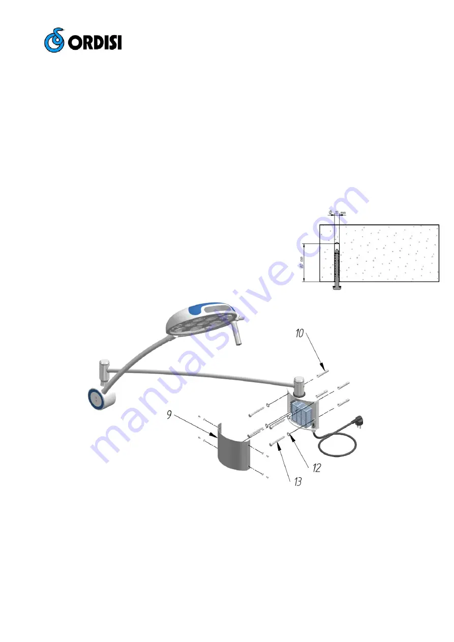
For fixing the wall plate, use the provided template to mark the holes and level 

it according to template. Four holes Ø10 mm and a depth of 80 mm. The height 

of  the  lamp  will  depend  on  the  work  area.  It  should  remain  at  a  distance  of 

approximately 80/100 cm from its workspace. If necessary, you can adjust the 

height  cutting  the  vertical  arm  nº 

8

.  It  is  recommended  to  install  it  between 

170cm and 200cm from the floor. 

Once  the  holes  are  made,  introduce  the  plug  Nº 

10

 and attach the mounting 

plate Nº 

11

 using the washers Nº 

12

 and screws Nº 

13

. Check the level of the 

lamp before. Finally mount the embellisher nº 

9


4.2.2. - ELECTRICAL INSTALLATION 


The electrical installation of the room where you plan to use the equipment should be in accordance with the rules UNE 

(CIS), as well as the Low Voltage Regulation.  

The plug socket where the equipment is going to be connected must be suitable for plugs according to standard rules 

UNE 20315 and / or DIN 49441, with terminals of 4'8 mm and lateral earthing.  


Fig. 2 – Wall plate installation. 

Содержание IG-65W

Страница 1: ...Mom 45 Revisi n 1 Fecha 2017 01 10 Tecnolog a 2 Nave 7 08780 Pallej Barcelona Spain 34 93 334 01 12 FAX 34 93 440 25 64 comercial ordisi com www ordisi com...

Страница 2: ...te con su distribuidor ORDISI m s pr ximo o directamente a nuestra Central ORDISI S A Tecnolog a 2 08780 Pallej Barcelona Espa a Tel 34 93 334 01 12 Fax 34 93 440 25 64 e mail comercial ordisi com 2 R...

Страница 3: ...ar a una distancia aproximada de unos 80 100 cm del rea de trabajo Si es necesario se podr ajustar la altura recortando el brazo vertical n 8 Por lo general se aconseja instalarla entre una distancia...

Страница 4: ...Hospital los Servicios de Mantenimiento deber n realizar las siguientes verificaciones 1 Verificar el funcionamiento general de la l mpara 2 Verificar movilidad del brazo y la c pula Ver punto 6 2 3 C...

Страница 5: ...e color 4 500K 5 CRI 95 Potencia 28 W de la c pula 300 mm campo de trabajo d10 260 mm campo de trabajo d50 130 mm Profundidad de campo L1 L2 170 cm 80 90cm Color RAL 9002 Peso aprox L mpara 19 5 Kg MO...

Страница 6: ...ve any requires about your IG 65P please contact your nearest ORDISI distributor or contact us to our head office directly ORDISI S A Tecnolog a 2 08780 Pallej Barcelona Espa a Tel 34 93 334 01 12 Fax...

Страница 7: ...g work by qualified staff For fixing the wall plate use the provided template to mark the holes and level it according to template Four holes 10 mm and a depth of 80 mm The height of the lamp will dep...

Страница 8: ...fore use If there is liquid inside you must wait until it has evaporated The handle located on the cupola is sterilizable by steam media at a temperature of 121 C with an exposure time of 20 minutes 6...

Страница 9: ...nation intensity adjustment from 20 000 to 65 000 lux Light source LED Colour temperature 4 500 K 5 CRI 95 Power 28W Light head 300 mm Field diameter d10 260 mm Field diameter d50 130 mm Depth of fiel...

Страница 10: ...P gina 10 de 11 8 PLANOS Y ESQUEMAS PLANS AND DRAWINGS Fig 6 Despiece de la c pula Exploded view of the cupola...

Страница 11: ...P gina 11 de 11 Fig 7 Despiece de brazos y anclaje a pared Exploded view of the arms...

Отзывы: