ORDISI IG-65C Скачать руководство пользователя страница 9


Página 9 de 13 


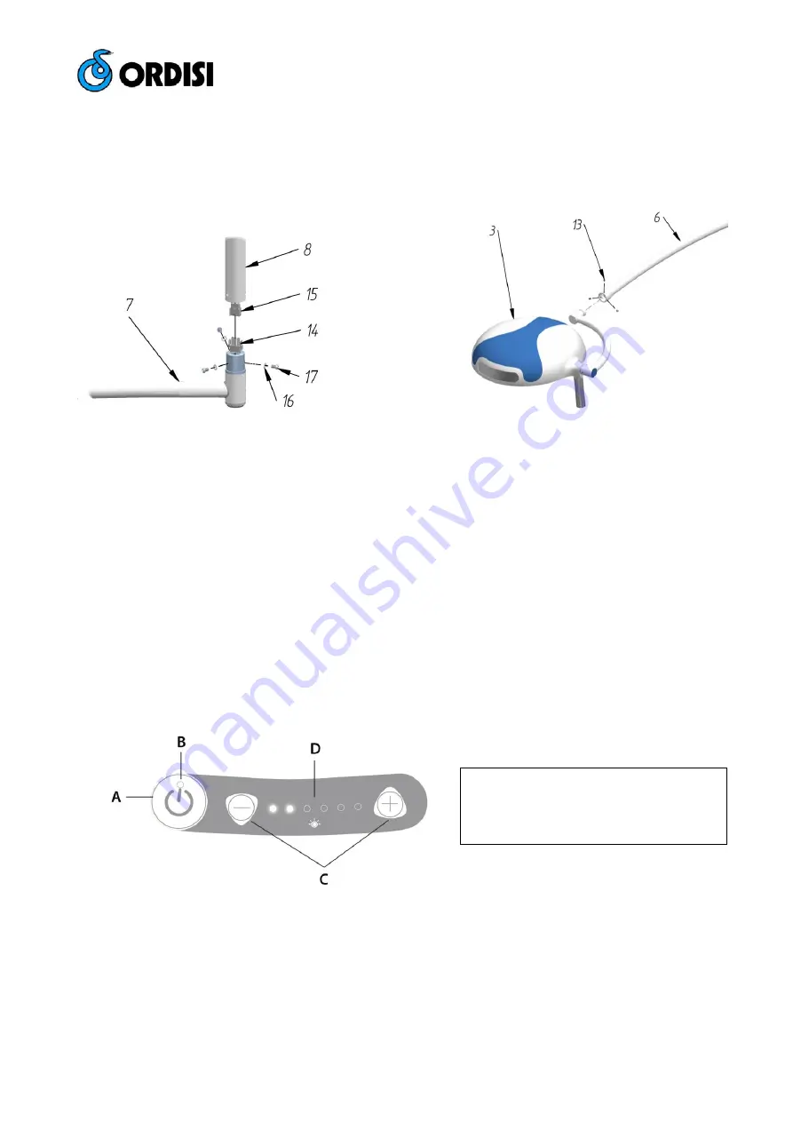
Once mounted the ceiling plate, assemble the horizontal arm nº 

7

 to vertical arm nº 

8

, join the electrical connectors nº 

14

 and 

nº 

15

 and fix by washers nº 

16

 and screws nº 

17 

(See Fig. 2a)


After that, assemble the cupola nº 

3

 with the arm nº 

6

. Hold the copula through the screws nº

 13

, and adjust it until you can 

move the copula with a gentle moving 

(See Fig. 2b)


4.2.3. - ELECTRICAL INSTALLATION 


Electrical installation of the room where you plan to use the equipment should be in accordance with the rules UNE 

(CEI60364-710), as well as the Low Voltage Regulation. Electrical installation of the room must include a fuse and a 

switch network for the simultaneous separation of the lamp with electric supply. 

It is essential that the lamp is properly grounded. Connect the network to the terminal located in the ceiling plate. 

Supported Voltage is 100-240V AC. 

Once you make the connections, check the proper operation of equipment and mount the embellisher nº 

9


4.3. - TURNING ON THE LAMP 


1.  Turn on the switch of the room. A red light should appear in the keypad when the lamp is connected. 


2.  Turn on the lamp, using the keypad No.

5

, and adjust the light intensity with the 

+

 and 

 buttons. 

(See Fig. 3)


3.  To change the position of the lamp, use the handle nº 

1

. Do that gently, avoiding brusque movements. 

4.  The lamp is adjusted at factory. If necessary a readjustment, 

see point 6.2.


4.4.-  RECOMENDATIONS FOR USE 


Move the lamp gently, avoiding brusque movements. 

If the lamp is not in use do not leave it on, since apart from wasting electricity you will reduce the useful life of the LED.


Fig. 2a – Assembly of the arms.   

Fig. 2b – Fork and cupola assembly


A

 – On / Off button 

B

 – On / Off Led indicator 

C

 – Luminous intensity adjustment buttons  

D

 – Luminous intensity Leds indicators  

Fig. 3 – Keypad 

Содержание IG-65C

Страница 1: ...Mom 41 Revisi n 1 Fecha 2017 01 10 Tecnolog a 2 Nave 7 08780 Pallej Barcelona Spain 34 93 334 01 12 FAX 34 93 440 25 64 comercial ordisi com www ordisi com...

Страница 2: ...sobre su l mpara contacte con su distribuidor ORDISI m s pr ximo o directamente a nuestra Central ORDISI S A Tecnolog a 2 08780 Pallej Barcelona Espa a Tel 34 93 334 01 12 Fax 34 93 440 25 64 e mail c...

Страница 3: ...ejecutados seg n DIN 1045 En otros tipos de techo la sujeci n deber ser proyectada en la obra La l mpara ha sido dise ada para una altura de techo de unos 275 cm para alturas distintas adaptar el bra...

Страница 4: ...laca anclaje Tensi n admitida de 100 240V AC Una vez hechas las conexiones comprobar el buen funcionamiento del equipo y montar el embellecedor n 9 4 3 PUESTA EN MARCHA 1 Poner el interruptor de la sa...

Страница 5: ...er n realizar las siguientes verificaciones 1 Verificar el funcionamiento general de la l mpara 2 Verificar movilidad del brazo y la c pula Ver punto 6 2 3 Comprobar la continuidad de la toma de tierr...

Страница 6: ...e color 4 500K 5 CRI 95 Potencia 28 W de la c pula 300 mm campo de trabajo d10 260 mm campo de trabajo d50 130 mm Profundidad de campo L1 L2 170 cm 80 90cm Color RAL 9002 Peso aprox L mpara 19 5 Kg MO...

Страница 7: ...uble free use If you have any requires about your IG 65C please contact your nearest ORDISI distributor or contact us to our head office directly ORDISI S A Tecnolog a 2 0780 Pallej Barcelona Espa a T...

Страница 8: ...manual is designed for concrete rooftops executed according to DIN 1045 In other types of roof the fixation must be projected in the building work The lamp has been designed for a ceiling height of 27...

Страница 9: ...k to the terminal located in the ceiling plate Supported Voltage is 100 240V AC Once you make the connections check the proper operation of equipment and mount the embellisher n 9 4 3 TURNING ON THE L...

Страница 10: ...dically carry out the following checks 1 Check the general working order of the lamp 2 Check the mobility of the arm and cupola See point 6 2 3 Check the equipment is still earthed and is correctly co...

Страница 11: ...r temperature 4 500 K 5 Led Power 28 W Screen diameter 300 mm Field diameter d10 260 cm Field diameter d50 130 cm Depth of field L1 L2 170 cm 80 90cm Colour RAL 9002 Approximate lamp Weight 19 5 Kg MO...

Страница 12: ...P gina 12 de 13 8 PLANOS Y ESQUEMAS PLANS AND DRAWINGS Fig 6 Despiece de la c pula Exploded view of the cupola...

Страница 13: ...P gina 13 de 13 Fig 7 Despiece de brazos y anclaje a techo Exploded view of the arms and ceiling mount...

Отзывы: