background image


All manuals and user guides at all-guides.com

Содержание AF1005

Страница 1: ...eluxe Smith Functional training Power cage combo CAUTION Read all precautions and instructions in this manual before using this equipment All manuals and user guides at all guides com a l l g u i d e...

Страница 2: ...pets to be unsupervised around the assembly or usage of this equipment Ensure all parts are in full working order before use Only one person should use the machine at any one time Do not use the equi...

Страница 3: ...All manuals and user guides at all guides com...

Страница 4: ...All manuals and user guides at all guides com...

Страница 5: ...All manuals and user guides at all guides com...

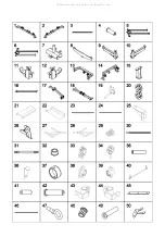
Страница 6: ...NECTION 1 19 PLATE SLIDER 2 20 DOUBLE PULLEY BLOCK 4 21 RIGHT IRON SHELL 1 22 LEFT IRON SHELL 1 23 DIRECT AXIS 2 24 GUIDE ROD 4 25 SIDE SUPPORT 4 26 FOOTBOARD 2 27 RIGHT HANDLE 1 28 LEFT HANDLE 1 29 S...

Страница 7: ...SHION RING 2 72 CABLE WITH ONE BALL 2 73 CABLE WITH TWO BALL 2 74 CABLE WITH NO BALL 2 75 PULLEY 38 76 BIG PULLEY 2 77 THIN BUFFER 2 78 ELLIPTIC BUFFER 4 79 HOIST HOOK 7 80 PIN WITH ROPE 2 81 HEX BOLT...

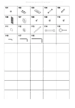
Страница 8: ...M12 30 2 101 NUT M12 2 102 TOP WEIGHT 2 103 WEIGHT 30 20 104 BOLT M10 70 WASHER 4 105 PIN 2 106 WEIGHT LABELING 2 107 BIG BEARING 4 108 SELF TAPPING SCREW M4 6 16 109 HEX SOCKET HEAD SCREWS M5 10 20 1...

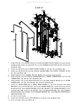
Страница 9: ...EP 01 1 Attach RIGHT UPRIGHT 5 to RIGHT BASE FRAME 1 with four bolt assemblies 81 2 Attach LEFT UPRIGHT 6 to LEFT BASE FRAME 2 with four bolt assemblies 81 All manuals and user guides at all guides co...

Страница 10: ...N 13 with two bolt assemblies 83 3 Attach UNDER CONNECTION 13 to RIGHT UPRIGHT 5 and RIGHT IRON SHELL 21 with two bolt assemblies 82 Attach UNDER CONNECTION 13 to LEFT UPRIGHT 6 and LEFT IRON SHELL 22...

Страница 11: ...GHT 5 and LEFT UPRIGHT 6 with four bolt assemblies 82 and four bolt assemblies 85 3 Attach REAR UPRIGHT 16 and TOP FRAME 17 to UPPER CONNECTION 14 with two bolt assemblies 85 4 Attach TOP FRAME 17 to...

Страница 12: ...ABLE PART 7 with two bolt assemblies 89 and attach ADJUSTABLE PART 7 to each UPRIGHT 3 with two FAST PINS 67 2 Attach four SMALL BUFFERS 68 to each UPRIGHT 3 with four bolt assemblies 87 Attach UPRIGH...

Страница 13: ...IDE SUPPORT 25 with bolt assembly 90 Do not tighten the bolts here Attach THICK BUFFER 69 RIGHT SAFETY 43 SPRING 29 THIN BUFFER 77 and PLATE SLIDER 19 to DIRECT AXIS 23 Attach SIDE SUPPORT 25 to DIREC...

Страница 14: ...13 with four bolt assemblies 82 Attach two ROUND BARS 31 to UNDER CONNECTION 13 with two bolt assemblies 90 and attach OP BAR 49 to each ROUND BAR 31 with bolt assembly 91 Attach ROUND PLUG 70 and CU...

Страница 15: ...ssemblies 96 6 Attach PULLEY 75 to each PULLEY BLOCK 57 and attach PULLEY BLOCK 57 to UPPER CONNECTION 14 with bolt assembly 97 and bolt assembly 98 7 Attach two GUIDE RODS 24 to RIGHT BASE FRAME 1 an...

Страница 16: ...2 Attach CABLE WITH NO BALL 74 attach one end of the cable to ADJUSTABLE PART 7 another end of the cable from O P Q R S and attach the end to UNDER CONNECTION 13 3 Attach CABLE WITH ONE BALL 72 the n...

Страница 17: ...73 with four HOIST HOOKS 79 3 Attach LAT PLATE 8 to CABLE WITH ONE BALL 72 with two HOIST HOOKS 79 Attach LOW ROW BAR 61 to LAT PLATE 8 with HOIST HOOK 79 4 Attach two HOOKS 51 to RIGHT UPRIGHT 5 and...

Страница 18: ...STEP 10 1 Attach WEIGHT LABELING 106 to TOP WEIGHT 102 and all WEIGHTS 103 All manuals and user guides at all guides com...
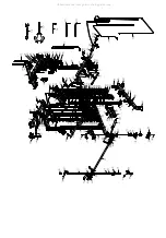
Страница 19: ...EP 11 If you only need to use the heavy 55KG please remove five WEIGHTS 103 and insert PLATE SUPPORT TUBES 4 at the bottom of GUIDE ROD 24 EXPLODED DRAWING All manuals and user guides at all guides co...

Страница 20: ...All manuals and user guides at all guides com...

Отзывы: