OPTRONIC FPDI200 Скачать руководство пользователя страница 5

Edition of

FSU201.411

07.08.2012

Version 1.2

Page 5 of 10

FSU201

3 Concept

The FSU201 analyzes the supplied video signal, and, if possible, assigns it to an internally stored con-
figuration. If the shown picture is not considered satisfactory, a number of parameters can be adjusted.
All changes done can be stored nonvolatile.
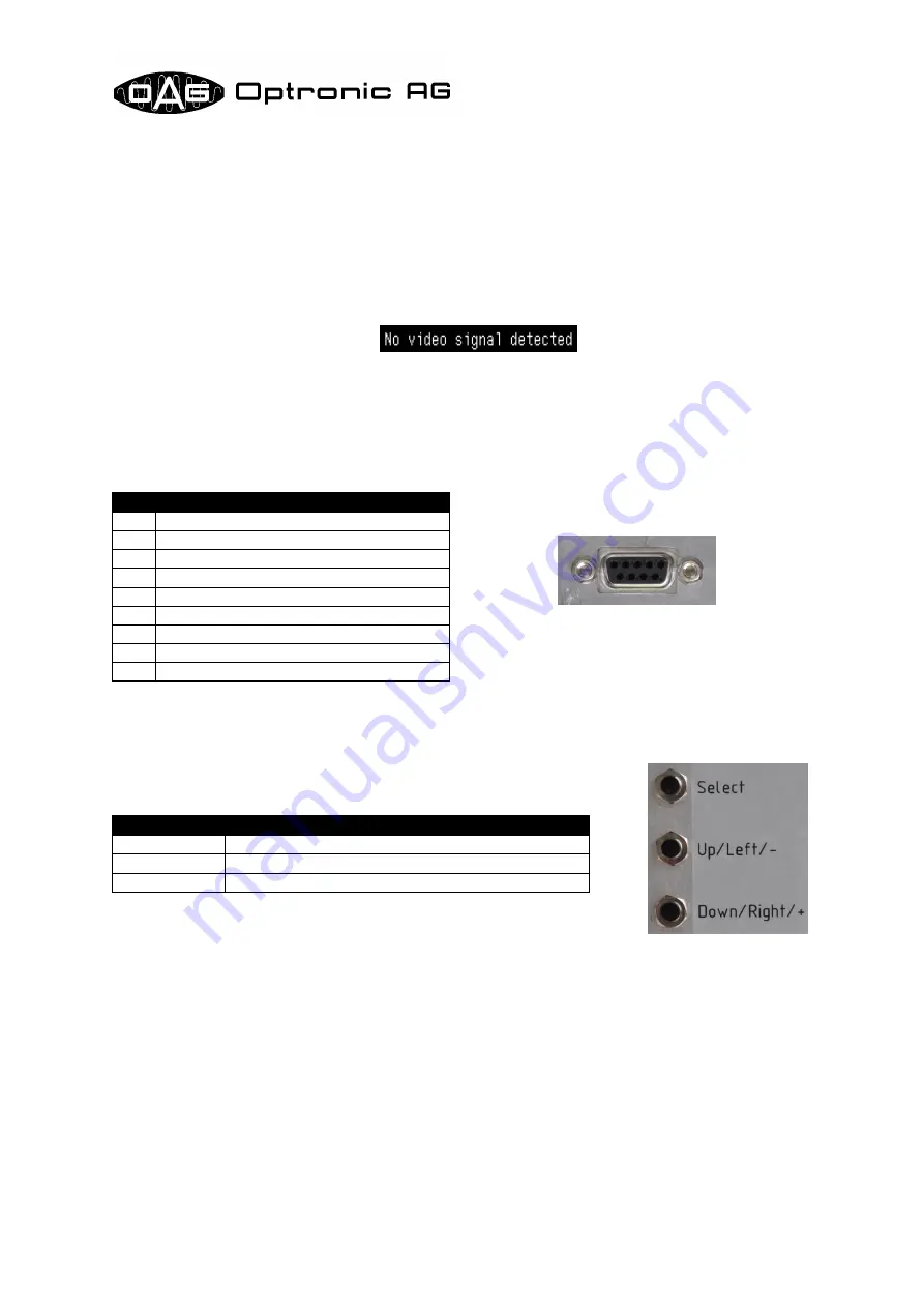
When the video signal is detected, the image is directly shown on the screen. The following message
is shown if no video signal is supplied:

4 Video Signal/Video Cable

The video signal must be supplied over the 9-pin connector on the back side of the device (refer to
Illustration 3). The signals GREEN, HSYNC and VSYNC must be digital TTL signals. The pin assign-
ment is shown in the following table:

5 Buttons

The device is operated by use of the three buttons mounted on the
back side (refer to Illustration 4):

Illustration 3: Video

connector

Pin

Assignment

1

GND (Ground)

2

+5V Power Supply

3

not used

4

GREEN (Green)

5

not used

6

not used

7

not used

8

HSYNC (Horizontal synchronization)

9

VSYNC (Vertical synchronization)

Illustration 4: But-

tons on the back side

of the device

Button

Usage

Select

Select, execute

Up/Left/-

Shift up or left, decrease value

Down/Right/+

Shift down or right, increase value

Содержание FPDI200

Страница 1: ...FSU201 Replacement for OPTRONIC CRT Monitors Unteregger Strasse 53 CH 9403 Goldach...

Страница 2: ...cs Excepted from this are product features which we in particular cases individually guaranty in writing We reserve the right to make amendments brought about as a result of technical advances Reprodu...

Страница 3: ...7 1 Show or Hide Version Information Show Version ON OFF ___________________ 7 7 2 Store Configuration ____________________________________________________ 7 7 3 Load Default Values___________________...

Страница 4: ...ry adjustments can be easily done by use of buttons on the back side of the device The con figuration process is easily operated by use of an on screen menu 2 Device Assembly The device consists of a...

Страница 5: ...l must be supplied over the 9 pin connector on the back side of the device refer to Illustration 3 The signals GREEN HSYNC and VSYNC must be digital TTL signals The pin assign ment is shown in the fol...

Страница 6: ...moved one position down By pressing button Select the selected func tion is activated or a sub menu is opened up The selected function stays active as long as the star remains at the corresponding en...

Страница 7: ...by use of main menu entry Load Default Values If storing the configuration was successful the message Configuration stored is shown 7 3 Load Default Values The standard configuration can be loaded by...

Страница 8: ...the upper or lower end position 7 7 Adjust Width The image width can be adjusted by use of main menu entry Adjust Width Move the star to this entry and activate the function by pressing button Select...

Страница 9: ...guration failed is shown The cause of this message is probably a hardware defect Please retry to store the configuration If the same mes sage is shown again the cause of the problem is a hard ware def...

Страница 10: ...411 07 08 2012 Version 1 2 Page 10 of 10 FSU201 List Of Modifications Date Reason 16 03 2010 Total number of pages corrected 07 08 2012 Modified due to changed buttons and new power supply 5V added t...

Отзывы: