CHAPTER 2: QUICK START
SNAP PAC S-Series User’s Guide
23
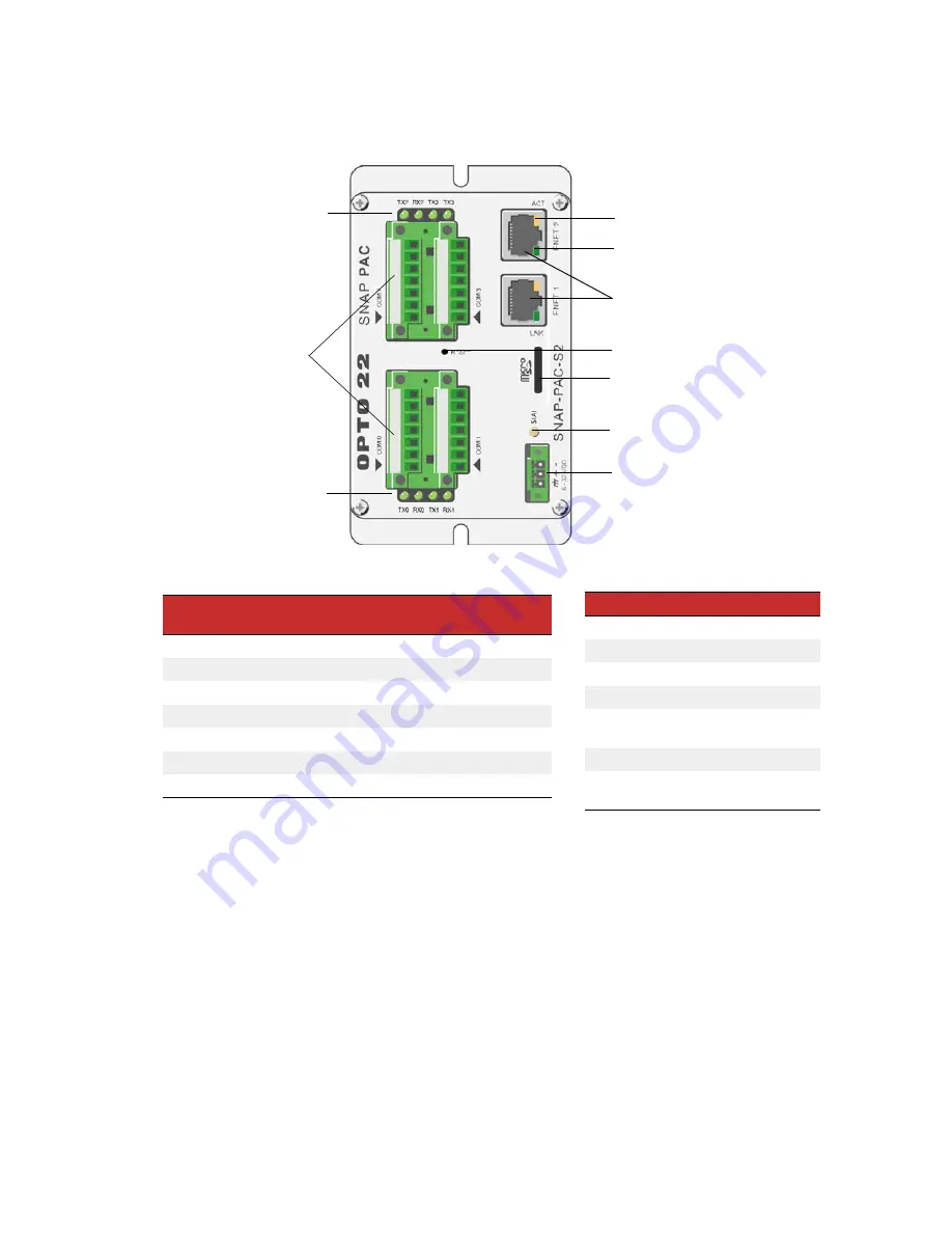
SNAP-PAC-S2
Status and Activity LEDs
Indicator
Description
TX0/RX0
Serial activity on port 0
TX1/RX1
Serial activity on port 1
TX2/RX2
Serial activity on port 2
TX3/RX3
Serial activity on port 3
STAT
Startup status and control
program operational status
ACT
Ethernet network activity
LINK
Link established with Ether-
net network
RS-485 and RS-232 Ports1
Pin
RS-232
Signal
Direction
RS-485
Signal
Direction
1
TX
Out
TX/RX+
In/Out
2
RX
In
TX/RX–
In/Out
3
COM
2
COM
2
4
RTS
Out
RX+ (4 wire)
In
5
CTS
In
RX- (4 wire)
In
6
DTR
Out
IRQ+
In
7
DCD
In
IRQ–
In
1 CAUTION
:
Do not use communication port connectors from a
legacy OptoControl controller*
. Legacy connectors will fit in a
SNAP-PAC-S2, but the pin orientation is different. Instead, use the
connectors supplied with the SNAP-PAC-S2 controller.
2
Isolated ground. (Each channel is isolated from the others.)
*Legacy OptoControl Controllers:
G4LC32
G4LC32SX
G4LC32ISA
G4LC32ISA-LT
M4
M4IO
M4RTU
SNAP-LCM4
SNAP-LCSX/PLUS
Independent 10/100 Mbps Ethernet
interfaces (RJ-45 connectors)
8–32 VDC input power
(pluggable 3-pin connector)
Ports 0 - 3 are each software
configurable as either
RS-232 (TX, RX, COM, DTR, DCD RTS,
CTS), or
RS-485 (2-wire, 4-wire, optional
termination, optional biasing).
Configure ports in PAC Manager.
Controller reset button
STAT LED
Activity LED (Yellow)
Link LED (Green)
Serial activity LEDs
Serial activity LEDs
MicroSD card slot
Содержание SNAP PAC S Series
Страница 6: ...SNAP PAC S Series User s Guide vi ...
Страница 37: ...CHAPTER 2 QUICK START SNAP PAC S Series User s Guide 31 SNAP PAC S1 W Antenna Dimensions ...
Страница 39: ...CHAPTER 2 QUICK START SNAP PAC S Series User s Guide 33 SNAP PAC S2 W Antenna Dimensions ...
Страница 70: ...SNAP PAC S Series User s Guide 64 ...


