background image


17 


2.3.2 

Encode  

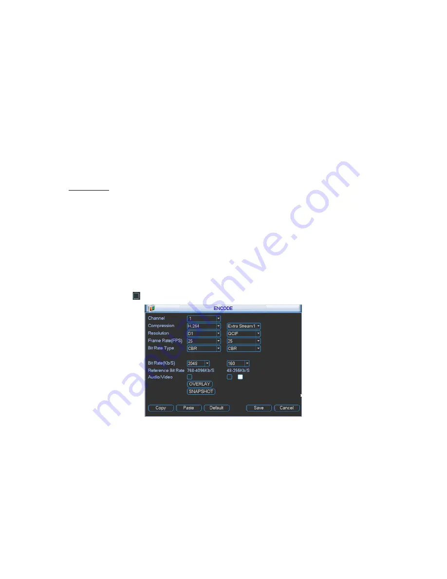
Encode interface is shown as in Figure 2-7.  


Channel: Select the channel you want. 


Compression: System supports H.264.  


Resolution: System supports various resolutions, you can select from the dropdown list. For this model, 

main stream supports D1/HD1/BCIF/CIF/QCIF. Please note the extra stream resolution may vary 

depending on series model. Refer to DVR model’s specification sheet or DVR user manual for details. 


Frame rate: ranges from 1f/s to 25f/s in NTSC mode and 1f/s to 30f/s in PAL mode.  

Note: 


Bit rate type: system supports two types: CBR and VBR. In VBR mode, you can set video quality. 

2 HDD Series  

If the 1-channel resolution is D1 and the frame rate is more than 6f/s (or 7f/s in NTSC), the extra stream frame 

rate shall be below 6f/s (or below 7f/s NTSC). 


Quality: There are six levels ranging from 1 to 6. The sixth level has the highest image quality. 


Audio/Video: you can enable or disable the video/audio. Please note the video is enabled for main stream 

by default. For extra stream, please enable video first and followed by audio if needed. 


Snapshot: Click snapshot button, this menu includes the four items: mode/image size/image 

quality/snapshot frequency. Please refer to chapter 2.3.3 for detailed information. 

Please highlight icon 

 to select the corresponding function. 


Figure 2-7


2.3.3 

Snapshot 

2.3.3.1  Schedule Snapshot – three menu interfaces should be setup to enable this feature: 

a.  In Encode interface, click snapshot button to input snapshot mode, size, quality and frequency. 

b.  In General interface please input upload interval. 

c.  In Schedule interface, please enable snapshot function. 


Please refer to the following figure for detail information. See Figure 2-8. 

Содержание VR EM

Страница 1: ...QUICK STARTUP GUIDE VR Series Embedded DVR Systems VR EM VR LT VR PRO ...

Страница 2: ... 1 7 Rear Panel 8 1 7 1 DVR Rear Panel 8 1 8 Connection Sample 10 Refer to the following figure for sample connection 10 1 8 1 LT Series 10 1 8 2 EM Series 10 1 8 3 PRO Series 11 1 9 Alarm Input and Output Connections 11 1 9 1 Alarm Input Port 11 1 9 2 Alarm Output Port 13 2 Overview of Navigation and Controls 14 2 1 Login Logout Main Menu 14 2 1 1 Login 14 2 1 2 Main Menu 14 2 1 3 Logout 15 2 1 4...

Страница 3: ...PTZ Setup 24 2 5 2 PTZ Operation 24 2 5 3 3D Intelligent Positioning Key 25 3 Web Operation 26 3 1 Network Connection 26 3 2 Login 26 3 3 Main Window 27 Check your Documentation and Application Disc that came in with your CCTV equipment for other manuals software and training video for your DVR system Contact your original DVR dealer seller or installer if you have any questions for software updat...

Страница 4: ...esktop or shelves Handle with care Do not apply power to the DVR until all the wiring and cable installation is done Do not place objects on top of the DVR to avoid damage Warranty is voided if damaged on the DVR is caused by improper storage 4 Qualified engineers needed All the troubleshooting and repair work should be done by the qualified service engineers only We are not liable for any problem...

Страница 5: ... 3 Cables and Settings Your DVR system was already pre inspected at the Optiview OEM facilities where all the settings and cables were already checked and verified by a service technician 1 4 HDD Installation Hard drive is already pre installed on your DVR system This section is only a reference in case you are adding more hard drive 1 4 1 2 or 4 HDD Series There are three model series for the VR ...

Страница 6: ...tion Use proper rack screws to fix the unit Please make sure the indoor temperature is below Please make sure there is 15cm 6 inches space around the device to guarantee sound and air ventilation 35 95 f Please install from the bottom to the top If there are other servers connected in the server rack please take precautionary measures to make sure server rack power is not overloaded After completi...

Страница 7: ...Multiple slow play speeds or normal playback Input number 8 Fast play Various fast speeds and normal playback Input number 7 Play previous I In playback mode playback the previous video Input number 9 Play Next I In playback mode playback the next video Input number 0 ESC ESC Go to previous menu or cancel current operation When playback click it to restore real time monitor mode Assistant Fn One w...

Страница 8: ...ing IR Receiver IR It is to receive the signal from the remote control CD ROM button Pop up or insert the CD 1 7 Rear Panel 1 7 1 DVR Rear Panel 4 8CH LT series rear panel 4 8CH VR LT Series 1 Video input 2 Audio input 3 Video CVBS output 4 Audio output 5 Network port 6 USB port 7 Video VGA output 8 Power input port 9 Alarm input alarm output RS485 port 10 Power button 16CH LT series rear panel VR...

Страница 9: ...cket PRO Series DVR rear panel is shown as below See Figure 1 5 VRPRO Series Rear Panel 1 Power button 2 Power input port 3 Fan 4 Loop video output 5 1st to 4th channel audio input 6 Video input 7 DB25 port 5th to 16th channel audio input port 8 Audio output 9 Bidirectional talk input port 10 Bidirectional talk output port 11 Network port 12 eSATA port 13 RS232 port 14 USB port 15 HDMI port 16 Vid...

Страница 10: ...10 1 8 Connection Sample Refer to the following figure for sample connection 1 8 1 LT Series 1 8 2 EM Series ...

Страница 11: ...e parallel connect the Ground of the DVR and the ground of the alarm detector Please connect the NC port of the alarm sensor to the DVR alarm input ALARM Use the same ground with that of DVR if you using external power to the alarm device Note VR4LT does not have Alarm Input output ports and no PTZ RS485 port For VR8LT DVR System Alarm Rear Panel for VR8LT Parameter Grounding Alarm Ground line Ala...

Страница 12: ...decoders For VREM Series In the second line from the left to the right 1 2 3 4 5 6 7 8 In the first line from the left to the right 9 10 11 12 13 14 15 16 ALARM 1 to ALARM 16 The alarm becomes active in low voltage In the second line from the left to the right NO1 C1 NO2 C2 In the first line the NO3 C3 The three groups of normal open activation outputs on off button Ground cable RS485 A B RS485 co...

Страница 13: ...puts Normal open or Normal close type Parallel connect COM end and GND end of the alarm detector Provide external power to the alarm detector Parallel connect the Ground of the DVR and the ground of the alarm detector Connect the NC port of the alarm sensor to the DVR alarm input ALARM Use the same ground with that of DVR if you use external power to the alarm device Use the controllable 12V power...

Страница 14: ...ssword 888888 administrator local only Username 666666 Passwords 666666 Lower authority user who can only monitor playback backup and etc Username default Password default hidden user You can use USB mouse front panel remote control or keyboard to input login information Click to switch between alpha numeric characters or change between upper lower case letters Note Three times login failure withi...

Страница 15: ...l automatically record video and resume previous working status after power failure 2 2 Live Viewing After you logged in by default the system will be in live viewing mode The system date time and channel name will be displayed on the screen If you want to change the system date and time refer to general settings Main Menu Setting General If you need to modify the channel name please refer to the ...

Страница 16: ...pes regular motion detection MD Alarm MD alarm Please highlight icon to select the corresponding function After completing all the settings click save button and the current menu goes back to the previous menu At the bottom of the menu are color bars indicating the type of record mode As a reference green color stands for regular recording yellow color stands for motion detection and red color sta...

Страница 17: ...below 6f s or below 7f s NTSC Quality There are six levels ranging from 1 to 6 The sixth level has the highest image quality Audio Video you can enable or disable the video audio Please note the video is enabled for main stream by default For extra stream please enable video first and followed by audio if needed Snapshot Click snapshot button this menu includes the four items mode image size image...

Страница 18: ...onding alarm occurred In Encode interface click snapshot button to input snapshot mode size quality and frequency In General interface please input upload interval In Detect interface please enable snapshot function for specified channels In Alarm interface please enable snapshot function for specified channels Please refer to the following figure for detail information See Figure 2 9 Figure 2 9 ...

Страница 19: ...erver See Figure 2 10 Please refer to the User s Manual included in the resource CD for detailed information Enable schedule snapshot or activation snapshot Chapter 2 3 3 and then system can upload the image file to the FTP server Figure 2 10 2 3 5 Snapshot Disk For selected series only Set one disk as snapshot Main menu Advanced HDD management and then click execute button See Figure 2 11 System ...

Страница 20: ...nal alarm recording file M Motion detection recording file Figure 2 13 Select search engine here You can see result here Double click file name you can view the image content There are max 100 files in one page Click here to view more Select a file and then click here to view image content Select playback mode here 4 ch or All channel Playback control bar Set search setup here Time Channel Type ...

Страница 21: ... m s in the time column and then click playback button the system will playback specific date and time based on your input information 2 3 7 4 Synchronized playback function when playback During playback process click numeral key system can switch to the corresponding channel video of the same time 2 3 7 5 Digital zoom When the system is in full screen playback mode press left button of your mouse...

Страница 22: ...ause In slow playback mode click this button to switch between play pause modes Previous next In playback mode you can click and to view previous or next video in current channel 2 3 7 9 Backward playback and frame by frame playback Button Illustration Remarks Backward play in playback interface In normal playback mode left click backward play button system begins backward playback Double click ba...

Страница 23: ... real time Fluency the system will in higher priority when you select Latency which means you may get frame loss when the network Internet connection speed is slow for video stream transfer because the DVR will try to maintain real time video speed at client end while sending video files remotely protect the fluency and continuity of video stream Network download System will prioritize the process...

Страница 24: ...p please click save button the system will go back to the previous OSD menu Figure 2 16 2 5 2 PTZ Operation In one window display mode right click mouse click Fn Button in the front panel or click Fn key in the remote control The interface is shown as in Figure 2 17 Click Pan Tilt Zoom the interface is shown as below See Error Reference source not found Here you can set the following items Step va...

Страница 25: ...is the 3D intelligent positioning key See Figure 2 20 Please note this function needs protocol supported by the PTZ camera and can only be operated by mouse Click this key system goes back to the single screen mode Drag the mouse in the screen to adjust section size It can activate PTZ automatically Figure 2 20 You can click set button in Error Reference source not found or click REC button in the...

Страница 26: ...control files or you can go to C Program Files webrec to delete Single folder 3 2 Login Open IE and input DVR address in the address column For example if your DVR IP is 10 10 3 16 please enter http 10 10 3 16 in IE address box System pops up warning information to ask you whether to install webrec cab control or not Please click yes button If you can t download the ActiveX file please modify your...

Страница 27: ...source CD included in your package for electronic version of the User s Manual Slight difference may be found in user interface All the design and software GUI are subject to change for improvement without prior written notice Please contact your original DVR dealer or seller if you have any questions for software updates or technical support issues Please check your Documentation and Application ...

Отзывы: