background image

Version 1.0.5 - 2020-12-09

125

Originalbetriebsanleitung

TX4414 DE | EN

T

X

4414

_par

ts.

fm

T

Schaltplan - Wiring diagram

Содержание OPTIturn 3432420

Страница 1: ...GB Operating Manual Version 1 0 5 Lathe Part no 3432420...

Страница 2: ...2 Emergency stop button 14 1 9 3 Protective cover of the headstock 14 1 9 4 Protective covers of drive 14 1 9 5 Lathe chuck protection with position switch 14 1 9 6 Chip guard shield 15 1 9 7 Prohibit...

Страница 3: ...Operation 4 1 Control and indicating elements 34 4 2 Safety 35 4 3 Switching on the machine 35 4 4 Switching off the machine 35 4 5 Resetting an emergency stop condition 35 4 6 Power failure Restorin...

Страница 4: ...the cutting speed 68 5 2 Influences on the cutting speed 68 5 3 Example for the determination of the required speed on your lathe 68 5 4 Table cutting speeds 69 6 Maintenance 6 1 Safety 70 6 1 1 Prepa...

Страница 5: ...andrad links Apron hand wheel left side 106 I Planschlitten Bettschlitten Cross slide bed slide 109 J Oberschlitten Top slide 111 K Maschinenbett kurz mit Bettbr cke Short machine bed with bed bridge...

Страница 6: ...intenance all maintenance works and functional tests are described which the operator must perform in regular intervals The illustration and information included in the present manual can possibly dev...

Страница 7: ...fic applicable regulations of each country must be observed If applicable necessary measures must be taken to comply with the country specific regula tions before commissioning the lathe Always keep t...

Страница 8: ...e serious injury or death CAUTION A danger or unsafe procedure that can cause personal injury or damage to property ATTENTION Situation that could cause damage to the lathe and the product and other t...

Страница 9: ...pproval of Maschinen Germany GmbH then the lathe is being used improperly We will not be held liable for any damages resulting from any operation which is not in accord ance with the intended use We e...

Страница 10: ...es must be propped up Use the steady rest or follow rest in conjunction with the tailstock spindle to support longer parts and prevent the workpiece from flapping around and flying away Risk of fire a...

Страница 11: ...fer to both the operation and maintenance of the lathe Determine and indicate clearly who will be responsible for the different activities on the lathe operation maintenance and repair Unclear respons...

Страница 12: ...ety standards that apply to the lathe the operation generally accepted engineering standards The operator must also check the personnel s knowledge level document the training instruction have attenda...

Страница 13: ...or files It is forbidden to use any hand tools on this machine 1 9 Safety devices Use the lathe only with properly functioning safety devices Stop the lathe immediately if there is a failure on the sa...

Страница 14: ...will continue to run for a while depending on the mass moment of inertia of the lathe chuck and the workpiece The emergency stop button brings the machine to a standstill Turn the knob to the right t...

Страница 15: ...nd oils or other corrosive substances from the operator side can also lead to a deteri oration of the polycarbonate windows The result is a reduced retention capability of the poly carbonate viewing p...

Страница 16: ...switch After activating the emergency stop button the drive on the lathe will shut off The spindle continues to rotate for a while depending on the mass moment of inertia of the spindle and workpiece...

Страница 17: ...activating the lathe ensure that this will neither endanger other persons nor cause damage to equipment Avoid any unsafe work methods Make sure that your work does not endanger anyone Clamp the workp...

Страница 18: ...in switch due to required works e g functional control 1 13 2 Using lifting equipment WARNING The use of unstable lifting and load suspension equipment that might break under load can cause severe inj...

Страница 19: ...ian prior to initial commissioning and after modifications or repairs prior to recommissioning and at set intervals The intervals must be set so that foreseeable defects can be detected in a timely ma...

Страница 20: ...mm 440 Main spindle bore mm 52 2 4 Work area Keep a work area of at least one metre around the machine free for operation and maintenance 2 5 Headstock Main spindle nose DIN ISO 702 2 No 6 Camlock Spi...

Страница 21: ...epends on production engi neering factors e g speed material and clamping conditions Module threads mm 44 pcs 0 25 3 75 D P threads 44 pcs 120 8 Lead screw pitch 6mm 2 9 Tailstock MT4 Quill diameter m...

Страница 22: ...re of the operator Characteristics of the working area e g size of damping behaviour other noise sources e g the number of machines other processes taking place in proximity and the period of time dur...

Страница 23: ...uspension equipment that might break under load can cause severe injuries or even death Check that the lifting and load suspension gear has sufficient load bearing capacity and that it is in perfect c...

Страница 24: ...ipt of delivery Check if all parts are firmly seated 3 3 Unpacking Install the machine close to its final position before unpacking If the packaging shows signs of having possibly been damaged during...

Страница 25: ...fted with slings The bedslide and the tailstock must be driven to the end of the machine bed in order to achieve a balanced load Clamp tailstock and top slide Wrap around the reinforcing bridges of la...

Страница 26: ...ape routes according to VDE 0100 part 729 as well as the environmental conditions for the operation of the machine The main switch of the machine must be freely accessible The machine must only be ins...

Страница 27: ...caused by incorrectly performed commissioning The machine can be placed in three different ways Anchor free assembly with vibration dampers anchored assembly ATTENTION Insufficient rigidity of the gr...

Страница 28: ...max load per element refers to the sum of static plus dynamic forces The machine must not be moved after the machine has been lowered Lift the machine with suitable lifting gear so that the SE85 eleme...

Страница 29: ...riginal instructions TX4414 GB TX4414_GB_3 fm Note The machine stands on the levelling nut 2 and not on the vibration damper 3 SE85 maximum load per element 1500 kg Levelling screw threaded rod M16x2...

Страница 30: ...are made Fit the previously prepared flat irons DIN EN 10058 70x20 with anchor rods DIN 529 M12x250 in line with the centres of the levelling points Lift the machine from the floor and fit the anchor...

Страница 31: ...four end adjusting screws 1 adjust until the machine spirit level displays an approximate value Move the carriage to the headstock and then to the tailstock and align the machine simulta neously with...

Страница 32: ...hine be placed into operation The headstock and feed box oil must be changed 150 hours after being filled for the first time then after every 2000 hours of operation Use the oil types recommended in t...

Страница 33: ...tive earth ground wire connection must be available Mains fuse 16 A ATTENTION Make sure that the direction of rotation of the drive motor and cooling lubricant pump is correct If the rotational direct...

Страница 34: ...sm 8 Machine lamp 7 Chip guard shield 10 Tailstock 9 Digital Position Indicator DP 700 or Digital Position Indicator NMS 300 DP700 Quick start guide on page 62 NMS 300 Quick start guide on page 65 12...

Страница 35: ...uators in the neutral position and close the lathe chuck protection 4 4 Switching off the machine CAUTION Only press the emergency stop button in a genuine emergency You should not use the emergency s...

Страница 36: ...want the turning direction to be anti clockwise The middle position is the neutral position 0 Move the shift lever up if you want the turning direction to be clockwise ATTENTION Wait until the lathe...

Страница 37: ...settings when the lathe is being completely stopped The selector levers are used to set the feed or the pitch required for the thread cutting Select the required feed direction 3 The thread table and...

Страница 38: ...eat Camlock DIN ISO 702 2 CAUTION Regularly check the closed status of the clamp bolt INFORMATION Mark each workpiece holder for instance by a nick in order to facilitate the recover of the precision...

Страница 39: ...d securely onto the lathe before they are machined The clamping force should be strong enough to ensure that the workpiece is moved correctly but not so tight that it is damaged or deformed Spare chuc...

Страница 40: ...erm speed max turning diame ter the information in the respective lathe chuck operating instructions and for special jaws the additional information on the respective drawing must be observed 4 11 2 I...

Страница 41: ...k The used lubricant should be of high quality and provided for high pressure bearing surfaces The lubricant should withstand the coolant and other chemicals Clamping jaws and jaw mounting screws are...

Страница 42: ...Operation Version 1 0 5 2020 12 09 42 Translation of original instruction TX4414 EN TX4414_GB_4 fm Clamping diameter too small Clamping on the largest possible diameter...

Страница 43: ...ON When clamping workpieces between the tips of the lathe while using a lathe dog the existing lathe chuck protection must be replaced with a circular lathe chuck protection Workpieces that require a...

Страница 44: ...ilable 4 14 1 Follow rest and steady rest Use steady rest or follow rest to support longer parts and prevent the workpiece from flapping around and flying away CAUTION When mounting a rest the rest is...

Страница 45: ...the required tool into the quill of the tailstock Use the scale on the sleeve to re adjust and or adjust the tool Clamp the quill with the clamping lever Use the hand wheel to move the sleeve back an...

Страница 46: ...e the stop Img 4 10 4 17 1 Straight turning Switch on the feed rod 8 Img 4 11 INFORMATION The feed rod drive can only be switched on if the gearbox levers are in the right position By switching on the...

Страница 47: ...itudinal feed feed rod 10 to the position for cross feed The engaging lever for thread cut ting 9 lead screw apron nut open must be set to the neutral position 4 18 Turning tapers 4 18 1 Cross adjustm...

Страница 48: ...Swivel the top slide to the required angle The infeed is achieved with the cross slide Loosen the four clamping screw at the top slide Swivel the top slide Clamp the top slide again 4 18 3 Turning of...

Страница 49: ...mula The top slide is twisted by this value then set the gauge to zero After removing the stop measure the bedslide will be aligned to the limit stop The gauge must indicate the calculated value Vo Th...

Страница 50: ...s are required on the face They are to be drilled before removing the lathe chuck The slaving of the workpiece is per formed by a pulling pin and a lathe carrier The calculated value Vr is the offset...

Страница 51: ...ten all screws Img 4 18 4 20 Standard values for cutting data when turning The better the cutting data are selected the better the turning result Some standard values for cutting speeds of different m...

Страница 52: ...ad cutting The thread cutting in longitudinal direction is carried out with the lead screw Set the desired pitch Set the engaging lever 5 for thread cutting on apron to the down position lead screw nu...

Страница 53: ...es that the operator has a good knowledge of turning and suf ficient experience NOTES Example of an external thread The workpiece diameter must have been turned to the diameter of the desired thread T...

Страница 54: ...gnation Profile Code letter Short term e g Application ISO threads M UN UNC UNF UNEF UNS M4x12 1 4 20UNC 2A 0 250 UNC 2A Machine tools and general mechanical engineering UNJ UNJ 1 4 20UNJ Aircraft and...

Страница 55: ...1 0 5 2020 12 09 55 Translation of original instruction TX4414 EN TX4414_GB_4 fm Round thread RD RD DIN 405 Fittings and for purposes of the fire brigade NPT NPT 1 11 NPT Fittings and tube joints Nut...

Страница 56: ...1 171 1 221 0 215 0 189 0 051 1 3 M 1 8 0 35 1 573 1 371 1 421 0 215 0 189 0 051 1 5 M 2 0 4 1 740 1 509 1 567 0 245 0 217 0 058 1 6 M 2 2 0 45 1 908 1 648 1 713 0 276 0 244 0 065 1 8 M 2 5 0 45 2 20...

Страница 57: ...25 706 26 211 2 147 1 894 0 505 26 5 M 36 4 33 402 31 093 31 670 2 454 2 165 0 577 32 M 42 4 5 39 077 36 479 37 129 2 760 2 436 0 650 37 5 M 48 5 5 44 752 41 866 41 866 3 067 2 706 0 722 43 M 56 5 5 5...

Страница 58: ...32 2 382 48 15 121 0 9 1 8 3 175 40 28 9 73 14 110 1 0 5 32 3 970 32 13 102 1 2 3 16 4 763 24 32 12 90 9 1 3 7 32 5 556 24 28 11 87 9 1 5 1 4 6 350 20 26 19 13 16 10 72 6 1 7 9 32 7 142 20 26 9 65 1...

Страница 59: ...ng chuck is selected and the machine spindle turns to the right the turning direction of the machine spindle is determined when you look into the spindle from the rear side If a left handed thread is...

Страница 60: ...e cooling agent is properly retrieved Respect the environment when dispos ing of lubricants and coolants Follow the manufacturer s disposal instructions 4 22 1 Cooling lubricants INFORMATION The lathe...

Страница 61: ...gives you information about the water hazard class They need to be environmentally friendly and workplace friendly Thus they need to be free of nitrite PCB chlorine and nitrosatable diethanolamine DE...

Страница 62: ...t Voltage to DP700 15 24VDC 10 Conforms to Low Voltage Directive External PSU Input Note Newall Measurements Systems reserves the right to change specifications without notice Warnings The mains suppl...

Страница 63: ...Digifind Reference Switches between Zero and Axis Preset modes Switches between Absolute and Incremental modes Information selection scrolls through options on Message display Function Menu Key Functi...

Страница 64: ...e numeric keypad to enter value value is in whole minutes of axis 1 to scroll through functions to return to main menu See full manual on website for more details to exit setup of axis 1 e S P A N O L...

Страница 65: ...WHUQDWLYHV If a Spherosyn300 encoder travels over 3 2m an error message will be displayed see full manual for details Turn off the power by disconnecting the power supply connector before you connect...

Страница 66: ...V LQ HUR PRGH Zero RI D LV RU QVXUH 106 is in set mode RI D LV RU hold QVXUH 106 is in set mode RI D LV RU Set Set LV VHOHFWLRQ NH Numeric keys QWHU NH OHDU NH Navigation keys 6ZLWFKHV EHWZHHQ HUR and...

Страница 67: ...sleep setup Reset setup Bright EnG Gb Generic 0 005 3 rad E 3 E 3 mminutes on 0 mmill lathe 0 01 0 02 0 05 E dia E 3 E 3 seconds mmediumm off no yes See full manual for more details nonE on func arc...

Страница 68: ...s result in cost efficient chipping 5 2 Influences on the cutting speed vc Cutting speed in m min t Service life in min The service life t is the period of time in minutes during which the cutting ins...

Страница 69: ...5 33 5 31 5 Rust resistant steel 600 700 P 10 80 75 71 71 67 63 56 53 50 50 47 5 45 45 42 5 40 33 5 33 5 31 5 31 5 30 28 Tool steel 1500 1800 High speed steel 9 7 5 6 5 6 4 5 3 6 4 3 2 2 5 P 10 45 42...

Страница 70: ...working area of the lathe with compressed air Cleaning inside the working area using compressed air may cause damages to the lathe 6 1 Safety WARNING The consequences of incorrect maintenance and repa...

Страница 71: ...ger for persons and that the lathe is not damaged 6 2 Inspection and maintenance The type and level of wear depends to a large extent on the individual usage and operating conditions Any indicated int...

Страница 72: ...r central lubrication system is supplied with the oil from the apron weekly Sight window Cleaning Clean the window with a suitable cleaning agent Oiling Oil all bare steel surfaces weekly Cooling lubr...

Страница 73: ...drive belt on page 76 For the first time after some operating hours according to demand Timing belt Feed gear Check Readjusting The machine was delivered with preloaded synchro nous belt After a few h...

Страница 74: ...screw the screw from the filler hole Close the drain hole if no more oil drains Fill up to the middle of the reference mark of the oil sight glass into the filler hole using a suitable con tainer Oper...

Страница 75: ...lamping wears off Shorten the clamping distance by adjusting the nut below the tailstock based on operator s historic values Electronics Electrical inspection Obligations of the operating company on p...

Страница 76: ...he working area of the lathe The machine is lacquered with a one component paint Take this criterion into account when selecting your cooling lubricant and cleaning the machine A one component lacquer...

Страница 77: ...nut on the top slide The spindle nut consists of two parts Loosen the axial securing screw next to the spindle nut Turn the spindle in clockwise direction until the spindle is locked Then turn it slig...

Страница 78: ...slide spindle nut 6 4 6 Adjusting the tapered gibs on the top slide and cross slide The play on the guide tracks is adjusted and reduced via the tapered gibs After setting the tapered gib check moveme...

Страница 79: ...ase by up to 50 percent of the nominal tensioning force A presumably securely clamped workpiece can then fall out of the chuck during processing Lubricate the lathe chuck Lubricate the lathe chuck at...

Страница 80: ...iece tapers while turning the shaft Img 6 8 Headstock Img 6 9 Headstock Clamp a precisely machined precisely ground test shaft with a length of 300 mm Attach a dial gauge on the workpiece holder Place...

Страница 81: ...chinen GmbH Dr Robert Pfleger Str 26 D 96103 Hallstadt can provide a customer service technician however the request for a customer service techni cian can only be made via your specialist dealer If t...

Страница 82: ...is an increase in nitrite content to more than 20 ppm mg 1 or nitrate content to more than 50 ppm mg 1 there is an increase in the N nitrosodiethanolamine NDELA to more than 5 ppm mg a CAUTION Comply...

Страница 83: ...nitial filing Measures in accordance manufacturer s recommendations 1 0 based on initial filing Replace cooling lubricant clean cooling lubricant circulation system Usage concentration Manual refracto...

Страница 84: ...ISO 702 2 Size no 5 DIN ISO 702 2 Size no 6 Maximum clamping diameter mm 200 200 200 minimum clamping diameter mm 13 Lathe chuck passage mm 50 50 65 max speed rpm 3000 max static clamping force S kN 3...

Страница 85: ...d with the manufacturer In order to avoid misuse it is necessary to read and understand the operating instructions before the first commissioning The operators must be qualified 7 3 1 Avoiding misuse...

Страница 86: ...again 7 4 Basic safety instructions The permissible speed as per VDI 3106 must be calculated for the machining allowance the maximum guide speed must not be exceeded The calculated values must be tes...

Страница 87: ...pping from the outside inwards and with increasing RPM the effective clamping force is reduced by the magnitude of the increasing centrifugal force the forces are opposed When the RPM limit is exceede...

Страница 88: ...red tensioning force for processing a workpiece the centrifugal force of the clamping jaws must be taken into account The permissible speeds can be determined in accordance with VDI Guideline 3106 Det...

Страница 89: ...6 the following also applies here The total centrifugal force Fc is dependent both on the sum of the masses of all jaws and on the center of gravity radius and the RPM ATTENTION For safety reasons in...

Страница 90: ...the clamping force will be 7 8 Notes on instruction of operating personnel We recommend that the business operating our manual chucks makes the operating instruc tions in particular the section Safety...

Страница 91: ...ge must be supported by the whole face 7 11 3 Mounting of the manual chuck Thoroughly clean the centering and the bearing surfaces of both parts and lubrify them with oil before placing the chuck onto...

Страница 92: ...ung Machines name Herstellungsdatum Date of manufacture Artikelnummer Article no Die Artikelnummer befindet sich in der Ersatzteilliste The article no is located in the spare parts list Die Seriennumm...

Страница 93: ...ts fm 8 4 Ersatzteilzeichnungen Spare part drawings A Spindelgetriebe Spindle gear 24 9 19 23 8 6 7 15 13 22 5 10 11 12 14 3 23 2 21 20 37 140 146 146 141 59 142 143 142 144 145 154 153 31 148 151 152...

Страница 94: ...nalbetriebsanleitung TX4414 DE EN TX4414_parts fm B Spindelgetriebe Spindle gear 23 73 66 75 65 77 35 74 64 72 71 70 75 69 68 67 31 37 35 35 57 58 56 61 55 59 31 62 60 37 54 44 48 51 50 50 45 38 43 41...

Страница 95: ...20 12 09 95 Originalbetriebsanleitung TX4414 DE EN TX4414_parts fm C Spindelgetriebe Spindle gear 116 113 119 118 159 115 1 136 137 138 128 132 131 129 133 134 130 135 160 123 122 124 125 124 126 121...

Страница 96: ...tung TX4414 DE EN TX4414_parts fm D Spindelgetriebe Spindle gear 89 90 159 111 80 79 107 159 111 79 156 81 82 83 84 85 88 78 107 105 99 98 95 104 108 103 107 112 92 107 109 100 82 110 93 87 107 155 86...

Страница 97: ...hnrad Gear 1 Z24 03432420127 28 Zahnrad Gear 1 Z48 03432420128 29 Zahnrad Gear 1 Z56 03432420129 30 Scheibe Washer 1 03432420130 31 Nadellager Needle bearing 7 20X28X13 03432420131 32 Scheibe Washer 1...

Страница 98: ...eibe Washer 2 03432420198 99 Sechskantschraube Hexagon screw 2 M6x12 100 Innensechskantschraube Socket head screw 3 ISO 4762 M6 x 10 101 O Ring O ring 1 DIN 3771 21 2x2 65 102 Gewindestift Grub screw...

Страница 99: ...201142 143 Zahnrad Gear 1 034324201143 144 Scheibe Washer 1 034324201144 145 Sechskantschraube Hexagon screw 1 M5x12 146 O Ring O ring 2 DIN 3771 12 5x1 8 147 Welle Shaft 1 034324201147 148 Zahnrad Ge...

Страница 100: ...00 Originalbetriebsanleitung TX4414 DE EN TX4414_parts fm E Vorschubgetriebe Feed gear 33 19 32 36 64 94 35 35 34 22 30 11 31 37 9 53 38 39 40 41 50 42 43 44 45 46 47 48 49 52 51 53 55 56 63 59 58 65...

Страница 101: ...rsion 1 0 5 2020 12 09 101 Originalbetriebsanleitung TX4414 DE EN TX4414_parts fm F Vorschubgetriebe Feed gear 95 93 11 2 10 3 1 7 4 5 6 10 9 27 7 28 29 8 8 26 11 12 11 23 22 13 19 23 18 25 16 17 24 1...

Страница 102: ...Originalbetriebsanleitung TX4414 DE EN TX4414_parts fm G Vorschubgetriebe Feed gear 89 20 91 91 92 91 96 91 99 73 90 98 79 64 88 76 76 80 84 81 83 81 83 79 19 64 73 90 98 68 72 71 70 69 90 98 73 99 7...

Страница 103: ...010 0406010 18 Dichtung Seal 1 TC28X35 5 0343242018 19 Innensechskantschraube Socket head screw 13 ISO 4762 M6 x 16 20 Innensechskantschraube Socket head screw 7 ISO 4762 M4 x 16 21 Innensechskantschr...

Страница 104: ...stift Grub screw 3 DIN 916 M4 x 10 64 Innensechskantschraube Socket head screw 11 ISO 4762 M5 x 12 65 Nadellager Needle bearing 1 3 0343242065 66 Dichtung Seal 1 TC40X47 5 0343242066 67 Nadellager Nee...

Страница 105: ...ew 4 M20x1 5 92 Geh use Housing 1 0343242092 93 Flansch Flange 1 0343242093 94 Flansch Flange 1 0343242094 95 Innensechskantschraube Socket head screw 3 ISO 4762 M6 x 12 96 lschauglas Oil sight glas 1...

Страница 106: ...TX4414 DE EN TX4414_parts fm H Schlosskasten Handrad links Apron hand wheel left side 48 24 22 21 36 49 20 12 26 29 41 1 43 14 10 53 43 5 17 45 28 27 18 8 39 38 51 51 55 8 13 23 25 48 56 11 50 9 32 33...

Страница 107: ...03432420417 18 Zahnritzel Gear shaft 1 03432420418 19 Flansch Flange 1 03432420419 20 Flansch Flange 1 03432420420 21 H lse Sleeve 1 03432420421 22 Handrad Handle 1 03432420422 24 Scheibe Washer 1 03...

Страница 108: ...Innensechskantschraube Socket head screw 1 ISO 4762 M8 x 12 48 Innensechskantschraube Socket head screw 2 ISO 4762 M10 x 16 49 Innensechskantschraube Socket head screw 4 ISO 4762 M6 x 10 50 Innensech...

Страница 109: ...09 109 Originalbetriebsanleitung TX4414 DE EN TX4414_parts fm I Planschlitten Bettschlitten Cross slide bed slide 1 2 3 4 4 5 6 7 8 9 10 11 12 13 14 15 15 16 17 15 18 19 20 21 22 23 24 25 26 27 28 29...

Страница 110: ...r Spring 1 03432420612 13 Lagerbock Bearing block 1 03432420613 14 Schmiernippel Lubrication cup 1 03432420614 15 Axiallager Trust bearing 3 03432420615 16 Buchse Bushing 1 03432420616 17 Zahnrad Gear...

Страница 111: ...Version 1 0 5 2020 12 09 111 Originalbetriebsanleitung TX4414 DE EN TX4414_parts fm J Oberschlitten Top slide 4 24 26 25 27 22 9 17 10 12 5 18 1 8 6 21 7 15 15 13 19 16 20 3 2 11 23 14...

Страница 112: ...3432420710 11 Spindelmutter Spindle nut 1 03432420711 12 Buchse Bushing 1 03432420712 13 Buchse Bushing 1 03432420713 14 Keilleiste Gib 1 03432420714 15 Handhebel Handle lever 2 03432420715 16 Bolzen...

Страница 113: ...ion 1 0 5 2020 12 09 113 Originalbetriebsanleitung TX4414 DE EN TX4414_parts fm K Maschinenbett kurz mit Bettbr cke Short machine bed with bed bridge 1 2 3 4 5 6 7 8 9 10 10 10 10 11 12 13 14 15 16 17...

Страница 114: ...sion 1 0 5 2020 12 09 114 Originalbetriebsanleitung TX4414 DE EN TX4414_parts fm U Maschinenbett lang ohne Bettbr cke Long machine bed without bed bridge 1 4 5 6 7 8 9 10 10 10 10 11 12 13 14 15 16 17...

Страница 115: ...Version 1 0 5 2020 12 09 115 Originalbetriebsanleitung TX4414 DE EN TX4414_parts fm L Maschinenbett Machine bed 19 20 21 22 23 24 25 26 27 28 29 30 31...

Страница 116: ...ut bed bridge 1380 034324208011 2 Bettbr cke Bed insert 1 for 1280 bed only 03432420802 3 Zahnstange Rack 1 03432420803 4 Bolzen Bolt 1 03432420804 5 Block Block 1 03432420805 6 Zahnstange Rack 1 0343...

Страница 117: ...2420822 23 Abdeckung Cover 1 03432420823 24 Abdeckung Cover 1 03432420824 25 Antriebsriemen Drive belt 1 03432420825 26 Abdeckung Cover 1 03432420826 27 Fusspedal Foot pedal 1 03432420827 28 Maschinen...

Страница 118: ...1 0 5 2020 12 09 118 Originalbetriebsanleitung TX4414 DE EN TX4414_parts fm N Reitstock Tailstock 17 16 28 5 15 20 27 13 14 10 19 30 18 35 32 36 34 33 36 11 3 1 2 12 4 31 6 21 22 28 7 23 21 8 9 24 25...

Страница 119: ...tric 1 03432420914 15 Spindelmutter Spindle nut 1 03432420915 16 Geh use Housing 1 03432420916 17 Grundplatte Base plate 1 03432420917 18 Platte Plate 1 03432420918 19 Ring Ring 1 03432420919 20 Innen...

Страница 120: ...aube Screw 3 034324201205 6 Endschalter Limit switch 1 034324201206 7 Platte Plate 1 034324201207 8 Drehfutterschutz Lathe chuck cover 1 034324201208 9 Platte Plate 1 034324201209 10 Ring Ring 1 03432...

Страница 121: ...low rest Pos Bezeichnung Designation Menge Gr sse Artikelnummer Qty Size Article no 1 Geh use Housing 1 034324201401 2 Bolzen Bolt 2 034324201402 3 Innensechskantschraube Socket head screw 2 ISO 4762...

Страница 122: ...ing 1 034324201302 3 Bolzen Bolt 3 034324201303 4 Spitze Center 3 034324201304 5 Gewndebolzen Threaded bolt 3 034324201305 6 Einstellmutter Ajust nut 3 034324201306 7 Bolzen Bolt 1 034324201307 8 Bolz...

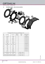
Страница 123: ...Version 1 0 5 2020 12 09 123 Originalbetriebsanleitung TX4414 DE EN TX4414_parts fm R Schaltplan Wiring diagram...

Страница 124: ...Version 1 0 5 2020 12 09 124 Originalbetriebsanleitung TX4414 DE EN TX4414_parts fm S Schaltplan Wiring diagram...

Страница 125: ...Version 1 0 5 2020 12 09 125 Originalbetriebsanleitung TX4414 DE EN TX4414_parts fm T Schaltplan Wiring diagram...

Страница 126: ...rheitssteuerung Relay safety control 1 3K5 1 Motorsch tz Spindel Rechtslauf Motor contactor spindle clockwise rotation 1 3RT6024 1BB40 12A DC24V 50 60HZ 1NO 1NC 034324203K5 3K5 2 Motorsch tz Spindel L...

Страница 127: ...a 150 Meropa 150 VG 100 CLP 100 Aral Degol BG 100 BP Energol GR XP 100 SPARTAN EP 100 Kl beroil GEM 1 100 Mobilgear 627 Shell Omala 100 Meropa 100 VG 68 CLP 68 Aral Degol BG 68 BP Energol GR XP 68 SPA...

Страница 128: ...r broches haute vitesse VG 68 Deol BG 68 Emergol HLP D68 Spartan EP 68 Druck l KLP 68 C Shell Omala 68 Fett f r Zentralschmierung Flie fett Grease for central lubrica tion Graisse pour lubrification c...

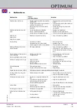
Страница 129: ...positions on feed gear can not be switched Gear is switchable but no feed Sliding gear drive feed Timing belt torn Check shift pins in the feed gear Check timing belt Have it checked by qualified Surf...

Страница 130: ...cracks due to improper cool ing Excessive play in the spindle bear ings oscillations occur Set greater wedge angle Cool uniformly Have the clearance in the spindle bearing arrangement re adjusted Turn...

Страница 131: ...y of the machine bed which feeds parallel to the tool axis Cross slide Slide on the slideway of the machine bed which feeds parallel to the tool axis Top slide Swivelling slide on the cross slide Tape...

Страница 132: ...y claims Using the product beyond the technical options and proper use in particular due to over straining of the machine Any defects arising by one s own fault due to faulty operations or if the oper...

Страница 133: ...t these components are disposed of separately and professionally In case of doubt please contact your municipal waste manage ment If appropriate call on the help of a specialist waste disposal company...

Страница 134: ...drive motor 10 6 4 Packing and loading Place the machine on 2 palettes to allow for removal transport 10 7 Disposal of new device packaging All used packaging materials and packaging aids from the mac...

Страница 135: ...recycling Your contribution to the correct disposal of this product will protect the environment and the public health Incorrect disposal constitutes a risk to the environment and public health Recycl...

Страница 136: ...plied EMC Directive 2014 30 EC Restriction of the use of certain hazardous substances in electrical and elec tronic equipment 2015 863 EU The following harmonized standards were applied EN ISO 23125 2...

Страница 137: ...plan 27 Interdepartmental transport 23 L Lathe chuck 85 Lathe chuck protection 14 Lifting equipment 18 Longitudinal turning 44 Lubrication 32 M Main switch 14 Maintenance 70 Maintenance work mechanica...

Страница 138: ...Version 1 0 5 2020 12 09 138 Translation of original instructions TX4414 EN TX4414_GBSIX fm...

Отзывы: