background image


Installation 
 

Important: Please use the installation procedure below.  Improper, or no 
operation may result if the start-up sequence is not correctly followed. 


Step 1 

Carefully unpack the contents of the shipping group.  

 
Step 2  

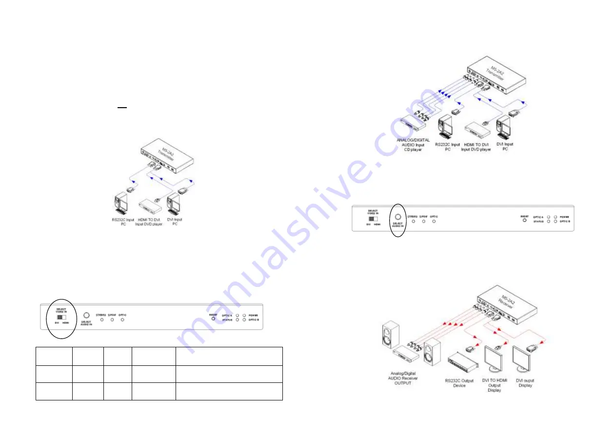
With  system  power  turned 

off

,  connect  the  Transmitter  module  to  the  DVI 

receptacle of PC or other video source equipment by a DVI copper cable or a 
HDMI to DVI cable. If necessary, connect the RS232 cable plugs to each  
D-sub 9-pin connector on PC and Transmitter module. 


Figure 2 

– Connection of DVI and RS232 Cable to Transmitter Module 


Select  video  input  with  the  video  source  equipment  by  the  switch  of  front 
panel.  

Notice  ; 

If 

“DVI”  input  is  selected,  HDCP  is  not  supported.  Therefore,  you 

have  to  choose 

“HDMI”,  if  the  video  source  equipment  is  compliant  with 

HDCP even though video output may be DVI. 


Figure 3 

– Selection of Video Input 


Selected 

Input 

DDC 

HDCP 

Maximum 

Length 

Recommended 

Fiber Type 

HDMI 

(direct) 

200 m 

Both SMF and MMF 

DVI 

(smart) 

2 km 

Both up to 500m 

Only SMF up to 2km 

 
1-3 Installation


Step 3 

Connect  the  Transmitter  module  to  the  audio  source  equipment  by  audio 
cables such as RCA, S/PDIF coaxial cable and S/PDIF optical fiber.  


Figure 4 

– Connection of Audio Cable to Transmitter Module 


You  can  select  one  of  different  3  audio  inputs  -  RCA,  S/PDIF(coaxial)  and 
S/PDIF(optical)  -  using  the  button  of  front  panel.  Audio  input  is  changed 
whenever  the  button  is  pushed.  Ensure  LED  of  the  selected  audio  input  lit 
ON. 


Figure 5 

– Selection of Audio Input


Step 4  

In  the  same  way  as  above,  connect  the  Receiver  module  to  the  display  by 
DVI copper cable and to the audio output equipments such as media receiver 
or  speaker  by  audio  cable.  The  RS232  devices  near  the  display  can  be 
connected by RS232 copper cable also.


Figure 6 

– Connection of Receiver Module 


1-4 Installation (continued)


Содержание M5-2A2-TR

Страница 1: ...port 1 6 Product Specifications 1 7 Warranty Information 1 8 Certifications 1 9 Pictorials Figure 1 Overall Digital Video Audio and Serial I O Optical Extender 1 1 Figure 2 Connection of DVI and RS232 Cable to Transmitter Module 1 3 Figure 3 Selection of Video Input 1 3 Figure 4 Connection of Audio Cable to Transmitter Module 1 4 Figure 5 Selection of Audio Input 1 4 Figure 6 Connection of Receive...

Страница 2: ...ation and no RFI EMI effects In addition a non trivial feature is that both of Single and Multimode optical fibers are applicable Shipping Group of M5 2A2 TR Digital Video Audio and RS232 optical extender Tx and Rx boxes One Transmitter module One Receiver module AC DC power adapter Two 12V 3A units including AC cord User s Manual Option Duplex LC Patch Cord Single or Multi mode glass fiber Figure...

Страница 3: ...tput may be DVI Figure 3 Selection of Video Input Selected Input DDC HDCP Maximum Length Recommended Fiber Type HDMI O direct O 200 m Both SMF and MMF DVI O smart X 2 km Both up to 500m Only SMF up to 2km 1 3 Installation Step 3 Connect the Transmitter module to the audio source equipment by audio cables such as RCA S PDIF coaxial cable and S PDIF optical fiber Figure 4 Connection of Audio Cable t...

Страница 4: ...splay displays only black screen Check that all AC and DC plugs and jacks used by external power supplies both Opticis and others are firmly connected Ensure that power LED lit ON Ensure that the Transmitter and Receiver modules connected correctly to the PC and display respectively Check if the PC and display are powered on and properly booted Reset the M5 2A2 TR using Reset button on Uplink and ...

Страница 5: ...ace the defective item or refund to customer the purchase price paid for the defective product All products that are replaced will become the property of Opticis Replacement products may be new or reconditioned Any replaced or repaired product or part has a ninety 90 day warranty or the reminder of the initial warranty period whichever is longer Opticis shall not be responsible for any software fi...

Страница 6: ...technical support check with the Opticis web site www opticis com or contact techsupp opticis com Certifications CE FCC Class 1 Laser Eye Safety Certification of Eye Safety This laser product is inside implemented by using 1310 1550nm LD Transceivers manufactured by Opticis Co Ltd which are all certified by CDRH FDA referred as classified in Laser Class 1 IEC60825 1 Caution Use of controls or adju...

Отзывы: