OPERATOR MANUAL
OSD2251P SERIES
4-PORT REDUNDANT RING
GIGABIT ETHERNET SWITCH WITH
PoE++ SOURCE
Страница 1: ...OPERATOR MANUAL OSD2251P SERIES 4 PORT REDUNDANT RING GIGABIT ETHERNET SWITCH WITH PoE SOURCE...
Страница 2: ......
Страница 3: ...NTERFACE 21 2 5 1 TERMINAL EMULATION SETUP 21 2 5 2 COMMAND LINE FUNCTIONS 22 3 MAINTENANCE 32 3 1 INTRODUCTION 32 3 2 EXTERNAL INSPECTION 32 3 3 ROUTINE MAINTENANCE 32 4 WARRANTY 33 4 1 WARRANTY PERI...
Страница 4: ...1 27 FIGURE 23 RING TOPOLOGY 27 FIGURE 24 FLOAT BACKUP ENABLED 2 28 FIGURE 25 FLOAT BACKUP ENABLED 3 28 FIGURE 26 FLOAT BACKUP DISABLED 1 29 FIGURE 27 FLOAT BACKUP DISABLED 2 30 FIGURE 28 FLOAT BACKUP...
Страница 5: ...y network utilising a mix of copper and fiber Industrial IP communications Self healing Gigabit Ethernet backbone networks Networks using Power over Ethernet devices such as cameras intercoms access c...
Страница 6: ...CAL SYSTEMS DESIGN DOC ID 10115303 OSD2251P OPERATOR MANUAL PAGE 6 1 2 TYPICAL CONFIGURATION Figure 1 below indicates a possible set up for an OSD2251P system FIGURE 1 OSD2251P TYPICAL RING CONFIGURAT...
Страница 7: ...onnectors RJ45 Alarms Ring to Bus High Temperature Alarm Interface Optoisolated MOSFET rated at 100mA 46V maximum PoE IEEE802 3af IEEE802 3at and PoE Operating Mode Alternative A B Pins 1 2 3 6 4 5 an...
Страница 8: ...a 4 way 5 08mm terminal block power connector and a 4way 3 5mm terminal block alarm connector Bottom Panel 4 Way DIP switch Type A USB connector and a Type B USB connector Each section will be descri...
Страница 9: ...ct may cause radio interference in which case the user may be required to take adequate measures OPTICAL OUTPUT OPERATION WARNING Laser Safety Class 1 Laser Product per IEC EN 60825 1 20011 standard C...
Страница 10: ...AL PAGE 10 2 2 2 OSD2251P DRAWINGS AND DIMENSIONS The OSD2251P is designed to be wall mounted onto a DIN Rail 35mm top hat fixture The unit dimensions excluding connectors SFPs etc is shown in Figure...
Страница 11: ...witch 2 2 4 POWER SUPPLY CONNECTIONS The OSD2251P requires external power to the Redundant DC Terminal Block Power Connector located at the top of the unit Always ensure that the power is off before a...
Страница 12: ...t out in Table 3 There are four pins on the 3 5mm terminal block used alarm output Maximum ratings the OSD2251P relay can drive is 100mA 46V max Note Alarm output has no polarity TABLE 3 ALARM CONNECT...
Страница 13: ...or See section 2 5 for further CLI information FIGURE 7 USB TYPE B CLI PORT To operate and control the OSD2251P using the CLI an OSD2251P driver will be required to be installed onto the PC being used...
Страница 14: ...OPTICAL SYSTEMS DESIGN DOC ID 10115303 OSD2251P OPERATOR MANUAL PAGE 14 FIGURE 8 WIN XP INSTALLATION...
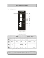
Страница 15: ...ABLE 4 LED FUNCTION No Function LED Colour Function On Blink Off Green Gr Am Amber Power No Power Power Ring Bus Initial Unmanaged Mode Ring Initializing Bus No Activity Activity No Link Active PoE No...
Страница 16: ...IGURE 11 OSD2251P 4 WAY DIP SWITCH TABLE 5 OSD2251P 4 WAY DIP SWITCH SETTINGS SWITCH NUMBER DESCRIPTION FUNCTION SWITCH POSITION 1 Port 4 Fiber Speed 100Mbps 1000Mbps ON OFF 2 Port 3 Fiber Speed 100Mb...
Страница 17: ...SFP is fully engaged and latched into position Inserting SFP Ensure that the SFP lever is in the locked position and insert into appropriate SFP port Gently push the SFP until it locks into place Remo...
Страница 18: ...fiber used must be 9 125 m singlemode fiber For multimode fiber connections fiber used must be 50 125 m or 62 125 m multimode fiber Plug in the appropriate connectors for system configuration RJ45 ca...
Страница 19: ...d line indicates the closed loop but more OSD2251P units can be connected to the ring as required using this topology Ensure that the switch settings for port 4 and 5 are set to 1000Mbps 1Gbps see Tab...
Страница 20: ...ANUAL PAGE 20 2 4 TYPE A USB PORT The Type A USB Port is used for uploading firmware updates All OSD2251P units will be shipped with the latest firmware already installed This port has no function for...
Страница 21: ...riate cable as specified in section 2 2 6 Using a terminal emulation program such as Hyperterminal a number of command lines specific to the OSD2251P can be implemented to check link node status ring...
Страница 22: ...t open when the unit is switched on while plugging in the USB cable however the command lines are functional The following table outlines the user available command line commands and their functions T...
Страница 23: ...hether the unit is either the Master or Slave on the ring bus in this case only one unit is connected thus displaying master The Master unit is determined by the unit with the lowest MAC address PORT3...
Страница 24: ...is either the Master or Slave on the ring bus Master is determined by the lowest MAC address PORT3 U_port Indicates the function of port 3 and its relation to the ring bus There are four possibilitie...
Страница 25: ...e is plugged into This enables the user to perform a node check on any OSD2251P unit from one location on the ring bus network The Node Check command requires the MAC address number for the node being...
Страница 26: ...PAGE 26 LOCAL NODE CHECK lnc Command Line FIGURE 21 LOCAL NODE CHECK This command line displays the running status of the local node that the USB cable is plugged into The information provided is the...
Страница 27: ...ed to the ring bus having Float Backup enabled SETTING_RESULT OK Displays the Float Backup enable has been successfully implemented local This points to the unit that the USB cable is plugged into on...
Страница 28: ...node 4 FIGURE 24 FLOAT BACKUP ENABLED 2 When the float backup is in enabled mode if the broken or disconnected branch is re established the backup branch will now be the last broken disconnected branc...
Страница 29: ...sable Displays all the units connected to the ring bus having Float Backup disabled SETTING_RESULT OK Displays the Float Backup disable has been successfully implemented local This points to the unit...
Страница 30: ...ode if the broken or disconnected branch is re established the backup branch will again be the furthest link from the smallest MAC addressed unit as shown in Figure 28 FIGURE 28 FLOAT BACKUP DISABLED...
Страница 31: ...L SYSTEMS DESIGN DOC ID 10115303 OSD2251P OPERATOR MANUAL PAGE 31 VERSION CHECK vc Command Line FIGURE 29 VERSION CHECK Displays the Software Version Number and Software ID Number installed on the OSD...
Страница 32: ...e damaged by failure of any portion of their support circuitry Some components within the unit are Electrostatic ES sensitive and Electrostatic Discharge ESD precautions should be taken when performin...
Страница 33: ...tive for all repairs 4 2 1 WARRANTY REPAIRS Return shipments to OSD shall be at customer s expense and freight back to the customer will be at OSD expense 4 2 2 OUT OF WARRANTY REPAIRS OSD reserves th...
Страница 34: ...uko Pl Warriewood 2102 P O Box 891 Mona Vale N S W Australia 2103 Telephone 61 2 9913 8540 Facsimile 61 2 9913 8735 Email sales osd com au Web Site www osd com au OPTIC L SYSTEMS DESIGN PTY LTD A B N...