


OPTICAL SYSTEMS DESIGN
DOC ID: 10112902
OSD350B OPERATOR MANUAL
PAGE 4
3.4
ALARM OUTPUTS
There are alarm outputs available on the rear panel via a 9-pin D female connector.
The alarm outputs are normally open circuit when each of the power supplies is operational.
If there is a power supply failure or excessive operating temperature, the alarm output is connected to
ground via a relay.
The pin out of the 9-pin D female connector is as follows:
Pin 3
PSU 1 Alarm Output
Pin 4
PSU 2 Alarm Output
Pin 7
Ground Return
All other pins are not used.
NOTE: The alarm indication is only available if the OSD921 power supply is installed.
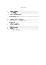
Содержание OSD350B
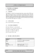
Страница 1: ...OPERATOR MANUAL OSD350B 12 CARD CHASSIS WITH DUAL REDUNDANT POWER WITH OSD921 AND NMS...
Страница 2: ......
Страница 9: ...OPTICAL SYSTEMS DESIGN DOC ID 10112902 OSD350B OPERATOR MANUAL PAGE 6...
Страница 10: ...OPTICAL SYSTEMS DESIGN DOC ID 10112902 OSD350B OPERATOR MANUAL PAGE 7...
Страница 11: ......