background image

2

VS375C/VS575C


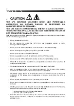
CAUTION:


!

THE UPS CONTAINS VOLTAGES WHICH ARE POTENTIALLY
HAZARDOUS. ALL REPAIRS SHOULD BE PERFORMED BY
QUALIFIED SERVICE PERSONNEL.

THE UPS HAS ITS OWN INTERNAL ENERGY SOURCE (BATTERY).
THE OUTPUT RECEPTACLES MAY BE LIVE EVEN WHEN THE UPS IS
NOT CONNECTED TO AN AC SUPPLY.

Safe and continuous operation of the UPS depends partially on the care taken by users. Please
observe the following precautions.


Do not disassemble the UPS.

  Do not attempt to power the UPS from any receptacle except a 2-pole

3-wire grounded receptacle.


Do not place the UPS near water or in environments of excessive humidity.


Do not allow liquid or any foreign objects to get inside the UPS.


Do not block air vents on the side of the UPS.


Do not plug appliances, such as hair dryers, into the UPS receptacles.


Do not place the UPS under direct sunshine or close to heat-emitting sources.

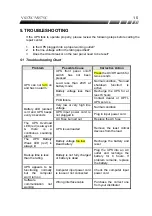
  This UPS is intended for installation in a temperature controlled, indoor area free of

conductive contaminants.


The socket-outlet shall be installed near the UPS and easily accessible.

  With the installation of the UPS it should be prevented, that the sum of the leakage

current of the UPS and the connected consumer exceeds 3.5mA.

  The battery supply should be disconnected in the plus and minus pole at the quick

connectors of the battery when maintenance or service work inside the UPS is
necessary.


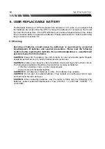
Do not dispose of batteries in a fire. The battery may explode.


Do not open or mutilate the battery or batteries, released electrolyte is harmful to the skin
and eyes.


A battery can present a risk of electric shock and high short circuit current. The following
precaution should be observed when working on batteries

* Remove watches, rings or other metal objects.

* Use tools with insulated handles.

z


To reduce the risk of fire, connect only to a circuit provided with 20 amperes maximum
branch circuit overcurrent protection in accordance with the National Electrical Code.
ANSI/NFPA 70.

Содержание VS375C

Страница 1: ...User s Guide Value Series Model VS375C VS575C ...

Страница 2: ... your UPS is on the rear panel You should note the serial number in the space provided below Retain this booklet as a permanent record of your purchase to aid in identification in the event of theft or loss Model No Serial No Purchase Date ...

Страница 3: ...y does not cover 1 Any product on which the serial number has been defaced modified or removed 2 Damage deterioration or malfunction resulting from a Accident misuse neglect fire water or other acts of nature unauthorized product modification or failure to follow instructions supplied with the product b Repair or attempted repair by anyone not authorized c The fault is result of accidental damage ...

Страница 4: ...gal rights and you may also have other rights which vary from state to state Some states do not allow limitations on implied warranties and or do not allow the exclusion of incidental or consequential damages so the above limitations and exclusions may not apply to you Limitations of Warranty for Australian States and Territories The Trade Practices Act 1974 and corresponding State and Territory F...

Страница 5: ...r life support equipment or direct care where failure of a UPS product could cause failure of or diminished effectiveness of the life support equipment or patient care Except as expressly provided for by the UPS Equipment Protection Policy EFFECTIVE October 1 1997 ...

Страница 6: ......
Страница 7: ...PRESENT A RISK OF ELECTRICAL SHOCK BURNS FROM HIGH SHORT CIRCUIT CURRENT FIRE OR EXPLOSION FROM VENTED GASES OBSERVE PROPER PRECAUTIONS WHEN REPLACING BATTERIES USE THE SAME NUMBER AND THE FOLLOWING TYPE BATTERIES SEALED LEAD ACID MAINTENANCE FREE VS375C 1 X 3 5AH 12V VS575C 1 X 3 8AH 12V PROPER DISPOSAL OF BATTERIES IS REQUIRED REFER TO YOUR LOCAL CODES FOR DISPOSAL REQUIREMENTS ...

Страница 8: ... UPS is intended for installation in a temperature controlled indoor area free of conductive contaminants The socket outlet shall be installed near the UPS and easily accessible With the installation of the UPS it should be prevented that the sum of the leakage current of the UPS and the connected consumer exceeds 3 5mA The battery supply should be disconnected in the plus and minus pole at the qu...

Страница 9: ...on reception which can be determined by turning the equipment off and on the user is encouraged to try to correct the interference by one or more of the following measures Reorient or relocate the receiving antenna Increase the separation between the equipment and the receiver Connect the equipment into an outlet on a circuit different from that to which the receiver is connected Consult the deale...

Страница 10: ...rotection 8 2 6 AC Input 8 2 7 Output Outlet 8 3 INSTALLATION AND OPERATION 3 1 Unpacking and Inspection 9 3 2 Placement 9 3 3 Determining How Much Equipment You Can Connect to Your UPS 9 3 4 Powering Up Your UPS 10 3 5 Connecting Your Equipment to the UPS 11 3 6 Operation and Function Test 11 3 7 Storage Instructions 12 4 SPECIFICATIONS 4 1 Electrical Specifications 13 4 2 Mechanical Specificatio...

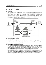
Страница 11: ... you plug the UPS into an AC outlet and turn it on it will automatically detect the incoming line frequency and configure itself to match that frequency 1 3 User Replaceable Battery Design The battery is the most critical part in a UPS The average lifetime of a battery is between 3 and 5 years The special user replaceable battery design of this UPS provides significant savings and gives the UPS an...

Страница 12: ...up Using OPTI SAFE Xtreme you can locally or remotely control the shutdown and startup of equipment connected to a UPS A customized schedule can be developed to meet your specific requirements 1 6 Data Line Surge Protection The built in data line surge suppression on the rear panel completes your system protection It provides an easy way to protect a network RJ45 or modem single line phone connect...

Страница 13: ... 3 When the UPS is operating in Battery mode you can silence the alarm by quickly pressing the power button This function is disabled when the UPS has a LOW BATTERY or OVERLOAD condition 4 Quickly press the button while the UPS is under AC mode and the UPS will perform an automatic self test procedure No load shut down function As a battery saving feature the UPS will automatically turn off if non...

Страница 14: ...usted To turn off the UPS Note that software and the communication cable are only available in certain areas Contact your local dealer for more information 2 5 Data Line Surge Protection In Out The data line surge protection on the rear panel provides an easy way to protect a network RJ45 or modem RJ11 connection from hazardous spikes Connect a network cable or a single line telephone into the In ...

Страница 15: ... be installed in a protected environment away from heat emitting appliances such as heaters or radiators Do not install this product where excessive moisture is present 3 The location should provide adequate air flow around the UPS with one inch minimum clearance on all sides for proper ventilation 3 3 Determining How Much Equipment You Can Connect to Your UPS 1 Make a list of all equipment that r...

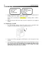
Страница 16: ...t as much VA capacity as your equipment requires 3 4 Powering Up Your UPS 1 For 100 110V 120V versions connect the power cord to a grounded 3 wire receptacle For 220V 230V 240V versions please refer to Sec 3 5 2 Power up the UPS by pressing the On Off switch on the front panel for three seconds 3 We recommend that you charge the battery for six 6 hours before first use of your UPS You may use the ...

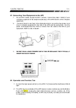
Страница 17: ...e the power cord supplied with the UPS to connect from the outlet of the UPS to your equipment Switch on the computer 3 DO NOT PLUG LASER PRINTERS INTO THE UPS BECAUSE THEY TYPICALLY DRAW TOO MUCH POWER 3 6 Operation and Function Test 1 Connect the input power and turn on the UPS The front panel Normal Mode LED will light 2 The UPS may be overloaded if the UPS buzzer sounds continuously and the Ba...

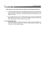
Страница 18: ...od idea to perform a backup function test at least once a month 4 If you unplug the power cord all models will beep once every 4 seconds and the Battery Mode LED will light You can press the Test Silence Button to silence the alarm Plug the power cord back in after a few seconds 3 7 Storage Instructions For extended storage in moderate climates the battery should be charged for 12 hours every 3 mo...

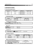
Страница 19: ...V 165 184 192V 275 276 276V Input Output Frequency Range Input 50 Hz 60 Hz 10 Output Inverter mode 50 Hz 60 Hz 0 3 Hz Wave Form AC Mode Sine wave Back Up Mode Step wave Transfer Time Power failure AC inverter 4 ms typical Spike Surge Protection Single pulse 8 20us Version Continuous Voltage Vrms Imax Joules 100 110 120 175V 6500A 1050 220 230 240 300V 6500A 1050 Data Line Surge Suppression Telepho...

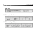
Страница 20: ...uous buzzer 4 2 Mechanical Specifications Product Name Dimensions Weight Kg W D H mm Net Gross VS375C 200 77 175 2 2 2 9 VS575C 200 77 175 2 3 3 0 4 3 Environmental Specifications Operating Storage and Shipment Temperature 0 40 C 32 104 F 20 60 C 4 140 F Humidity 5 90 non condensing 5 90 non condensing Altitude 3 000 m 10 000 ft Max 12 000 m 40 000 ft Max ...

Страница 21: ...w or very high line voltage Normal condition UPS input power cord is not plugged in Plug in input power cord Battery LED amber is lit and UPS beeps every 4 seconds AC Fuse burned out Replace the AC fuse The UPS Overload LED red is always lit there is a continuous sounding alarm UPS is overloaded Remove the least critical devices from the load The UPS Battery Weak LED red is always lit Battery volt...

Страница 22: ...the batteries Keep unknowledgeable i e unauthorized personnel away from the batteries CAUTION Except for the battery the unit contains no user serviceable parts Repairs should be performed only by factory trained service personnel CAUTION A battery can present a risk of electrical shock and high short circuit current The following precautions should be observed when working on batteries 1 Remove w...

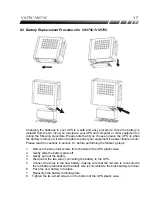
Страница 23: ... failure occurs Please read the cautions in section 6 1 before performing the following steps 1 Remove the two small screws from the side of the UPS plastic case 2 Gently slide the battery plate off 3 Gently pull out the battery 4 Disconnect the two wires connecting the battery to the UPS 5 Connect the wires to the new battery making sure that the red wire is connected to the red battery terminal ...

Страница 24: ...crewdriver to take out the fuse socket 2 Take out the broken fuse from the fuse socket 3 Throw away the broken fuse 4 Use the slotted screwdriver to push out the spare fuse 5 Put the spare fuse into the fuse socket 6 Push the fuse socket into the AC input socket ...

Отзывы: