HOBO State Data Logger (UX90-001x) Manual
1-800-LOGGERS 3
www.onsetcomp.com
option). Once the logger has been offloaded and
disconnected from the computer, the LCD will turn off
automatically after 2 hours. The LCD will turn back on the
next time the logger is connected to the computer.
Setting up the Logger
Use HOBOware to set up the logger, including selecting the
start and stop logging options, configuring the sensors, and
entering scaling factors as necessary. It may be helpful to set up
the logger to start at a specific date/time or with a push button
stop and then bring it to the location where you will mount it to
connect any external devices and test the connections before
logging begins.
1.
Connect the logger and open the Launch Logger window
. To
connect the logger to a computer, plug the small end of the
USB cable into the side of the logger and the large end into a
USB port on the computer. Click the Launch icon on the
HOBOware toolbar or select Launch from the Device menu.
Important:
USB 2.0 specifications do not guarantee
operation outside the range of 0°C (32°F) to 50°C (122°F).
2.
Configure the sensor.
Choose either the internal or external
sensor. Enter the name and select the state description as
necessary or select the sensor type.
The internal sensor can be configured to log:
•
State.
This records how long an event lasts by storing the
date and time when the state or switch changes (logic
state high to low or low to high). The logger checks every
second for a state change, but will only record a time-
stamped value when the state change occurs. One state
change to the next represents the event duration.
•
Runtime.
The logger checks the state of the switch once
every second. At the end of each logging interval, the
logger records how many seconds the line was in the logic
low state.
The external channel can be configured to log state or
runtime as described above or the following:
•
Pulse.
This records the number of pulse signals per logging
interval (the logger records a pulse signal when the input
transitions to the logic low). There are built-in scaling
factors you can select for supported devices and sensors,
or you can set your own scaling when you select raw pulse
counts. Click the Advanced button to adjust the maximum
pulse frequency and lockout time as needed.
Note:
Setting
maximum pulse frequency to 50 Hz will reduce battery
life.
•
Event.
This records the date and time when a connected
relay switch or logic low transition occurs (the logger
records an event when the input transitions to the logic
low). This is useful if you need to know when a switch
closes, but the duration of the closure is not important.
Click the Advanced button to adjust the lockout time to
debounce switches as needed.
3.
Configure optional filters as necessary.
Click the Filter
button to create additional filtered data series based on the
sensor configuration. Any filtered series will be automatically
available upon reading out the logger.
4.
Set the units to display on the LCD screen.
For State and
Runtime sensors, select either Time or %. For external
sensors, you can either use the default units or enter your
own units up to three characters.
5.
If the logger is configured to record pulse or runtime,
choose a logging interval from 1 second to a maximum of
18 hours, 12 minutes, and 15 seconds.
6.
Choose when to start logging:
•
Now.
Logging begins immediately.
•
At Interval.
Logging will begin at the next even interval
(available when logging pulse or runtime).
•
On Date/Time.
Logging will begin at a date and time you
specify.
•
Push Button.
Logging will begin once you press the
Start/Stop logging button for 3 seconds.
7.
Choose when to stop logging:
•
When Memory Fills.
Logging will end once the logger
memory is full.
•
Never (Wrapping).
The logger will continue recording data
indefinitely, with newest data overwriting the oldest.
•
Push Button.
Logging will end once you press the
Start/Stop logging button for 3 seconds. Note that if you
also choose Push Button to start logging, then you will not
be able to stop logging until 5 minutes after logging
begins.
•
Specific Stop Time.
Logging will end at a date and time
you specify.
8.
Select any other logging options as desired and click Start to
finish the launch configuration.
The status of the launch will
be displayed on the LCD screen, unless you select the option
to “Turn LCD off.”
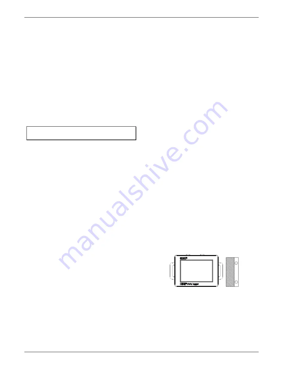
Using the Magnet (Internal Sensor)
The logger contains an internal reed switch that can be used
with the included magnet as the input to the logger. This
configuration can be used to determine when a door or
window is open or closed. The magnet must be oriented as
shown below, positioned to the right side of the logger when
the LCD screen is facing up.
Using the Input Cable (External Sensor)
The 2.5 mm input cable included with the logger can be used to
measure contact closures and allows the logger to be mounted
remotely from the contacts. Connect the contacts to the black
and white wires, and plug the other end of the cable into the
external input jack on the bottom of the logger. Do not connect
the contacts to any other devices or cables.
If the external sensor was configured to record raw pulse
counts or events in HOBOware, there is also an option to


