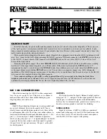
R534
P522
R533
P211a
JL913a
VCT
IID
L-IID
NCAR-5864
P613a
P711a
JL912a
RIGHT
1
30
IID
VCT
P521
LEFT
TX-2100
ADJUSTMENT AND CONFIRMATION PROCEDURES 1
Idling current adjustment
Before Idling adjustment, turn the trimming resistors R533 and R534 to counter clockwise.
Connect the DC voltmeter to terminals P521 and P522.
After turn POWER to ON, adjust the trimming resistors R533 and R534 so that the reading of
voltmeter becomes 2.0 mV.
After adjustment, attach the top cover.
Confirm the voltage of points above after about five minutes.
When less than 7.0 mV, readjust the resistors above so that the voltage becomes 7.0 mV.
When 7.0 mV to 9.0 mV, you are not necessary to adjust.
When more than 9.0 mV, readjust the resistors above so that the voltage becomes 9.0 mV.
Confirmation of protection circuit
1. Confirmation of operation of speaker relay
Confirm that the speaker relays turn ON approximate. 5 seconds after the power switch is turned ON.
Confirm that the speaker relays turn OFF immediately after the power switch is turned OFF.
2. Confirmation of DC detection circuit
Press and hold down CD button, then press DIRECT TUNING button.
After "TEST- " on the FL tube light on, press TAPE 1 button to set the unit to "TEST-1 00".
Apply DC 1.5 to 3V to CD terminal with no load.
Confirm that the speaker relay turns OFF.
Apply DC -1.5 to -3V to CD terminal with no load.
Confirm that the speaker relay turns OFF.
Caution: Don't apply DC voltage more than 1 sec..