ONEAC CDR45I Series Power Conditioner, Installation Guide, 913-521 Rev. A
15
Installation
Principle of Operation
The following brief description of the ONEAC CDR45I Series Power
Conditioner’s principle of operation is provided to assist in the proper
installation and operation of your power conditioner.
Interconnections and Operations:
1. AC power is supplied to the power conditioner by connection to the input
terminal block. When AC power is supplied to this terminal block via the
service panel circuit breaker, the Input Power ON LED is illuminated.
2. Three phase AC power is connected from the terminal block to the main
input circuit breaker. The input circuit breaker for this product utilizes
modular current trip rating plugs which are inserted or plugged into a single
molded case circuit breaker frame. An undervoltage release accessory is
installed in the input breaker as a means of control.
3. A separate multi-tapped primary, 24 Vac secondary, transformer is utilized
for power control, and supplied from the input terminal block (L1 and L2).
The primaries of this transformer are fuse protected (2A, 600 V rating). The
secondary of this transformer is also fuse protected (1A, 250 V rating).
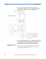
4. The 24 Vac control circuit energizes the undervoltage release accessory
within the main input circuit breaker when the Emergency Mains Off
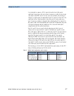
(EMO) circuit is closed. An external connection for the EMO circuit is
provided by means of a circular plastic connector (CPC) located on the
lower right back panel above the convenience receptacles. The power
conditioner is shipped with a shorting plug secured to the panel mounted
CPC. The shorting plug has a wire jumper across pins 3 and 4 of the CPC. A
spare mating CPC is provided with the unit in the spares compartment to
allow for this shorting plug to be replaced with any series connected NC
contact string. (See
“Emergency Mains Off” on page 26
for detailed
description of operation.)
5. In order to turn ON the main input circuit breaker, the EMO circuit must be
closed so that the undervoltage release accessory is energized.
Содержание CDR45I Series
Страница 6: ...Safety Information 6 ONEAC CDR45I Series Power Conditioner Installation Guide 913 521 Rev A...
Страница 10: ...List of Figures 10 ONEAC CDR45I Series Power Conditioner Installation Guide 913 521 Rev...
Страница 32: ...Installation Output Connections 32 ONEAC CDR45I Series Power Conditioner Installation Guide 913 521 Rev A...
Страница 36: ...Maintenance Fuse Replacement 36 ONEAC CDR45I Series Power Conditioner Installation Guide 913 521 Rev A...
Страница 38: ...Operation of Additional Features 38 ONEAC CDR45I Series Power Conditioner Installation Guide 913 521 Rev A...
Страница 40: ...Physical Views 40 ONEAC CDR45I Series Power Conditioner Installation Guide 913 521 Rev A...
Страница 48: ...Specifications CDR45I Schematics 48 ONEAC CDR45I Series Power Conditioner Installation Guide 913 521 Rev A...


