


Setting Sensing
130
ZW-8000/7000/5000
User's Manual
Setting the Measurement Area
Setting the start and end positions of the measurement area and mask area on the selected measurement
area allows the area used for measurement to be limited.
Cutting out the areas where there is no measurement object makes it possible to measure the object with
stability.
When the measurement object is set to “Glass,” measurement may not be performed correctly as
measurement will be influenced by reflection from the rear surface. If this happens, set the measurement area
of each measurement surface so that they can be correctly measured.
The measurement area can be set by dragging the start axis and end axis displayed on the sensing monitor
screen.
Set the start and end positions of the measurement area so that the start position is greater than the end
position.
Multiviewer Explore
: [Bank Group] | [(Bank Data Name)] (double click)
→
Edit pane
: [Sensing setting] icon (
)
→
Sensing settings window : [Measurement area 1] or [Measurement area 2]
• In the sensing monitor window, you can check whether the waveform of received light is obtained correctly as set
up.
Displaying Measured Values and Received Light Waveform p.99
• The amount of emitted light cannot be exactly same as setting value [%] and actual control value [%] due to the
control resolution difference of Sensor Controller (0.1[
μ
s]). The minimum value of control resolution is 0.1[
μ
s].
• When the amount of emitted light (maximum) [%]/100 for the measurement cycle [
μ
s]* is set to fall below 10
μ
s, the
actual control amount of emitted light (maximum) is 10
μ
s.
Item
Setting item
Setting value
Description
Measurement
area 1
Measurement
area (start)
Measuring range
of Sensor Head
[mm]
Set the measurement start position for the selected measurement area.
When the window for the selected measurement area is open, the start
position can also be edited by dragging the start line on the line bright monitor.
Measurement
area (end)
Measuring range
of Sensor Head
[mm]
Set the measurement end position for the selected measurement area.
When the window for the selected measurement area is open, the end
position can also be edited by dragging the end line on the line bright monitor.
Measurement
area 2
* Only in the 2
area mode
Measurement
area (start)
Measuring range
of Sensor Head
[mm]
Set the measurement start position for the selected measurement area 2.
When the window for the selected measurement area is open, the start
position can also be edited by dragging the start line on the line bright monitor
Measurement
area (end)
Measuring range
of Sensor Head
[mm]
Set the measurement end position for the selected measurement area 2.
When the window for the selected measurement area is open, the end
position can also be edited by dragging the end line on the line bright monitor.
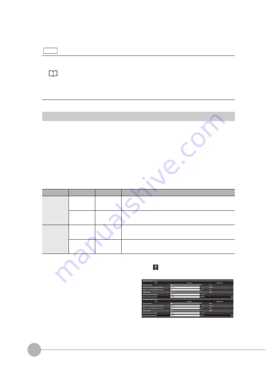
1
Set the values of [Measurement area (start)]
and [Measurement area (end)].
Note
Содержание ZW-7000 Series
Страница 22: ...20 ZW 8000 7000 5000 User s Manual Index 329 Revision History 332 ...
Страница 23: ...ZW 8000 7000 5000 User s Manual 1 21 ...
Страница 54: ...Basic Operations for Displaying Measurement Results 52 ZW 8000 7000 5000 User s Manual MEMO ...
Страница 96: ...Saving a project 94 ZW 8000 7000 5000 User s Manual MEMO ...
Страница 192: ...Saving The Settings 190 ZW 8000 7000 5000 User s Manual MEMO ...
Страница 280: ...Connecting by No protocol Communications 278 ZW 8000 7000 5000 User s Manual MEMO ...
Страница 281: ...8 Troubleshooting Troubleshooting 8 1 Error Messages 280 8 2 Troubleshooting 282 ...
Страница 288: ...Troubleshooting 286 ZW 8000 7000 5000 User s Manual MEMO ...
Страница 289: ...9 APPENDICES APPENDICES 9 1 Specifications and External Dimensions 288 9 2 Laser safety 323 9 3 Firmware Update 324 ...
Страница 330: ...Firmware Update 328 ZW 8000 7000 5000 User s Manual MEMO ...
Страница 333: ...Index ZW 8000 7000 5000 User s Manual 331 9 APPENDICES ...
Страница 335: ......


