


- 5 -
4
450ms max
50ms max
M1
M2
MOD
F = Frequency monitoring threshold
Normal operating mode: 2Hz (fixed)
Maintenance mode:
Low-speed monitoring
frequency preset value
TYPE G9SX-LM224-F10-
Safety speed detection output (see note3)
II
15ms max.
450ms max.
50ms max.
TYPE G9SX-LM224-F10-
Ratings and Specifications
Ratings
Rated supply voltage
Power
input
ITEM
TYPE G9SX-LM224-F10-
ITEM
Operating voltage range
Rated power consumption
(See Note1)
24 VDC
-15% to +10% of rated supply voltage
5 W max.
Safety input
Feedback/reset input
Mode selector input
Rotation detection input
Operating voltage: 20.4VDC to 26.4VDC,
Internal impedance : approx. 2.8kohm
(see note2)
Operating voltage: 20.4VDC to 26.4VDC,
Internal impedance : approx. 2.8kohm
(see note2)
Input frequency:1kHz max.
Inputs
Outputs
Safety solid-state output(see note3)
External indicator output
P channel MOS FET output
Load current: 0.8A DC max.
(see note4, 5)
P channel MOS FET output
Load current: 0.3A DC max.
PNP transistor output
Load current: 100mA DC max.
Specifications and Performance
Over voltage category (IEC/EN 60664-1)
Operating time (OFF to ON state)
(see note6, 7,12)
Response time (ON to OFF state)
(see note6,12)
50ms max. (With Safety input/Enable input ON)
100ms max. (With Logical AND connection input ON)
Allowable time for switching Mode selector inputs
(see note 9)
Mode selector input response time (see note 10)
ON-state residual voltage
OFF-state leakage current
3.0V max. (Safety solid-state outputs,
Safety speed detection outputs and Auxiliary outputs)
0.1mA max. (Safety solid-state outputs,
Safety speed detection outputs and Auxiliary outputs)
100m max.
Maximum cable length for logical connection inputs
and Safety inputs
Within minus 10% of the set value
Frequency: 10 to 55 to 10Hz,
Amplitude: 0.375mm half amplitude (0.75mm double amplitude)
-10 to +55
°
C (No freezing or condensation)
25 to 85%RH
Approx. 240 g
4 units max.(see note8)
Number of units connected per Logical connection output.
20 units max.
Total number of units connected with Logical connection
(see note 8)
5 units max.
Number of units connected in series with Logical connection
Accuracy tolerance of Low speed detection frequency(see note11)
100ms min.
Reset input time
Vibration resistance
Mechanical shock resistance
Ambient temperature
Ambient humidity
Weight
300 m/s
2
(destruction), 100 m/s
2
(malfunction)
(10) This is the time required for Safety inputs/Enable inputs to be switched
following a switch of Mode selector inputs. (While MOD indicator lights
up, Enable inputs are valid state. And while MOD indicator is off, Safety
inputs are valid state.)
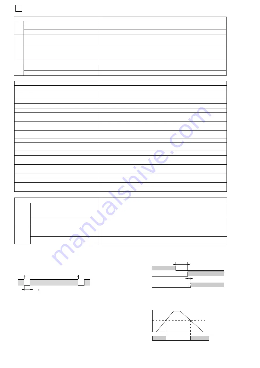
(11) The diagram below shows the relationship between the Low-speed
monitoring frequency and Safety speed detection outputs.
The frequency (F) has a tolerance of - 10%.
This accuracy tolerance does not include any characteristics of proximity
sensors.
(12) Operating time and response time do not include the frequency
detection time and the time affected by the characteristics of proximity
sensors. For response performance of the entire system, see
"Response performance regarding speed detection".
Insulation Specifications
Item
20Mohm Min. (250VDC megger)
20Mohm Min. (250VDC megger)
500VAC for 1min
500VAC for 1min
Insulation
resistance
Dielectric
strength
- Between all terminals connected together
and DIN rail.
- Between Logical AND connection terminals,
and Power supply input terminals and other
input and output terminals connected together.
- Between all terminals connected together
and DIN rail.
- Between Logical AND input terminals, and
Power supply input terminals and other
input and output terminals connected
together.
typ.100ms
OFF
ON
360
s
Max.
Note:
(1) Power consumption of loads not included.
(2) Ensure that more current supply than the minimum load current required
for the connected control device is provided.
(3) While safety outputs are in the ON state, signal sequence shown below is
output continuously for diagnosis.
When using the safety outputs as input signals to control devices (e.i.
programmable controller), consider the off pulse below.
(4) The following derating is required when units are mounted
side-by-side. - 0.4 A max. load current
(5) The following derating is required when inductive load is conneted
to safety outputs.
- IEC/EN60947-5-1 DC-13: 0.8A
- UL508 Pilot Duty: 0.5A
(6) When multiple units are connected through logical connections, the total
operating/response time will be the sum of the operating/response time of
each unit connected.
(7) This is the time required to turn ON safety solid-state outputs when
required conditions are met.
(8) The number of TYPE G9SX-EX401-
(Expansion Unit) and TYPE
G9SX-EX041-T-
(Expansion Unit, Off-delayed model) not included.
(9) This is the time allowed for switching Mode selector inputs. If it exceeds
450ms, G9SX-LM will detect it as a failure.
Safety input is valid state
Enable input is valid state
F
(time)
(Hz)
safety speed ON
detection output OFF


