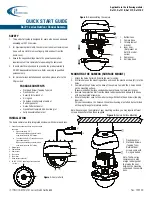
manualshive.com logo in svg
background image

No.18S111-03 


1/70 

STC-MBS500POE / STC-MCS500POE 
Product Specifications and User’s Guide 


GigE Vision 

Monochrome / Color CMOS PoE Camera 


STC-MBS500POE


(5M / 

Monochrome

STC-MCS500POE


(5M / 

Color


Product Specifications and User’s Guide 


Содержание STC-MBS500POE

Страница 1: ...3 1 70 STC MBS500POE STC MCS500POE Product Specifications and User s Guide GigE Vision Monochrome Color CMOS PoE Camera STC MBS500POE 5M Monochrome STC MCS500POE 5M Color Product Specifications and Us...

Страница 2: ...5 4 Environmental Specifications 15 6 Connector Specifications 16 6 1 RJ45 Connector 16 6 2 Power and Control Signal Connector 17 Opto isolated input 19 Opto isolated output 19 Open Collector GPIO 20...

Страница 3: ...igger Signal 32 9 3 Edge Preset Trigger Mode 33 Timing 33 Exposure Timing with Positive Polarity Trigger Signal 34 Exposure Timing with the Negative Polarity Trigger signal 34 9 4 Edge Preset Trigger...

Страница 4: ...on setting 46 10 8 Gamma correction 47 10 9 ROI Region of Interest 47 10 10 Pixel Format 48 10 11 Decimation 48 10 12 Trigger 49 Trigger signal processing procedure 49 10 13 Image Flip 50 10 14 LUT Co...

Страница 5: ...11 7 LogicBlockControl 63 11 8 SoftwareSignalControl 63 11 9 CounterAndTimerControl 63 11 10 EventControl 64 11 11 UserSetControl 64 11 12 ChunkDataControl 65 11 13 ActionControl 65 11 14 FileAccessC...

Страница 6: ...es incorrectly About Graphic symbols This symbol shows general prohibition This symbol shows completion or instruction Environment condition Warning Do not use flammable or explosiveness atmospheres T...

Страница 7: ...of electrification or accident caused by malfunction Do not put combustibles near the camera This will cause of fire Do not use without usage that is specified in the specifications for this camera Th...

Страница 8: ...y the power that satisfies the specified in specifications for the camera The defective pixels may appear due to the sensor characteristics Use below recommend materials or equivalent materials to cle...

Страница 9: ...mer in the documentation and or other materials provided with the distribution 3 The name of the author may not be used to endorse or promote products derived from this software without specific prior...

Страница 10: ...S500POE 4 1 Features GigE Interface Support PoE Power over Ethernet Small robust camera housing Maximum frame rate Full resolution 21 95 fps 5M 8bits CMOS Global Shutter Up to 2 048 Defective Pixel Co...

Страница 11: ...ain 0 dB Sensitivity 1 230 Lux 420 Lux Exposure Time 1 seconds to 16 777 seconds Default 45 345 seconds Gain Analog Gain 0 to 20 8 dB Default 0 dB Digital Gain x1 to x3 Default x1 ROI Horizontal 264 t...

Страница 12: ...e camera operates with external power when power suppling by external power supply and PoE to camera at same time Camera Setting Environment Parameter Setting Parameter Setting Gain Up 0 dB Light Sour...

Страница 13: ...No 18S111 03 13 70 STC MBS500POE STC MCS500POE Product Specifications and User s Guide 5 2 Spectral Sensitivity Characteristics STC MBS500POE STC MCS500POE without IR Cut Filter...

Страница 14: ...cal Filter IR Cut Filter Optical Center Accuracy Positional accuracy in Horizontal and Vertical directions 0 5 mm Rotational accuracy of Horizontal and Vertical 1 5 deg Material Aluminum Alloy AC Lens...

Страница 15: ...5 RH No condensation Vibration 20 Hz to 200 Hz to 20 Hz 5 min cycle acceleration 10 G XYZ 3 directions 30 min each Shock Acceleration 38 G half amplitude 6 ms XYZ 3 directions 3 times each Standard Co...

Страница 16: ...supported NIC Network Switcher and Ethernet cable Check the setting of NIC and Network Switcher being used is 1GB transferring Green LED Yellow LED Status Green Light ON Yellow Light OFF Power ON 1GB...

Страница 17: ...GenICam command Pin No Signal Name IN OUT Voltage 1 POWER IN IN 10 8 to 26 4 Vdc 2 Opto isolated in Line0 IN Low Smaller than 1 0 V High 3 0 to 26 4 V Potential difference between TRG_in and Opt Isola...

Страница 18: ...nternal The image transferring starts signal is out 6 Sensor Read Out FVAL Frame valid HIGH state signal is out 7 Debounced Line0 Debounced Line0 signal is out 8 Debounced Line2 Debounced Line2 signal...

Страница 19: ...ications and User s Guide Opto isolated input The camera has current limiting circuit on camera The current limiting resistor does not necessary Opto isolated output It is necessary to have current li...

Страница 20: ...outside of camera to keep current less than 50 mA When using as input current limiting resistor does not necessary However camera does not have current limiting circuit on camera The camera inside cir...

Страница 21: ...e out Camera internal processing Output signals FrameTriggerWait ExposureActive DebounceLine0 2 FramTriggerInternal SensorReadOut Timer0 Debounce External hardware Trigger delay Tdelay 1 Parameter Exp...

Страница 22: ...rigger Timed Exposure Mode and Positive Edge Trigger Software trigger Trigger delay Exposure Image out Camera internal processing Output signals FrameTriggerWait ExposureActive FramTriggerInternal Sen...

Страница 23: ...oto coupler or transistor Please refers example measurement of delay in below 6 2 6 1 External Trigger Signal Delay Positive polarity trigger signal External Trigger Signal External Trigger Signal wit...

Страница 24: ...trigger signal Pull up voltage Tdelay Minimum active pulse duration Pull up voltage Tdelay Minimum active pulse duration 3 3 V 8 2 seconds 6 seconds 3 3 V 47 seconds 6 seconds 12 V 4 6 seconds 3 secon...

Страница 25: ...arity trigger signal Pull up voltage Tdelay Minimum active pulse duration Pull up voltage Tdelay Minimum active pulse duration 3 3 V 3 9 seconds 6 seconds 3 3 V 0 6 seconds 6 seconds 12 V 3 8 seconds...

Страница 26: ...6 70 STC MBS500POE STC MCS500POE Product Specifications and User s Guide 7 Dimensions 7 1 STC MBS500POE Unit mm 15 20 2 M3 Depth3 5 29 29 28 5 53 42 49 15 20 16 1 20 7 5 7 1 32UNF C mount 4 M3 Depth3...

Страница 27: ...11 03 27 70 STC MBS500POE STC MCS500POE Product Specifications and User s Guide 7 2 STC MCS500POE Unit mm 15 20 2 M3 Depth3 5 29 29 1 32UNF C mount 28 5 53 42 49 15 20 16 4 M3 Depth3 5 1 20 2 M2 Depth...

Страница 28: ...nsor Information 8 1 Pixel Transferring Image STC MBS500POE Monochrome Pixel m of Data mth pixel being transferred STC MCS500POE Color Pixel 11 of Data Pixel 12 of Data Pixel 21 of Data Pixel 22 of Da...

Страница 29: ...No 18S111 03 29 70 STC MBS500POE STC MCS500POE Product Specifications and User s Guide 9 Camera Operational Modes 9 1 Normal Mode Expose Image out Exposure Time The exposure time for each line is same...

Страница 30: ...edge of trigger signal The expose period is high states of trigger signal In this trigger mode with negative polarity the expose starts at falling edge of trigger signal and stops at rising edge of tr...

Страница 31: ...sconds 0 to 1H Note 1 The trigger signal will be removed by filtering if active pulse width of input trigger signal is less than Line Debounce Time setting time Please input trigger signal has more th...

Страница 32: ...seconds 0 to 1H Note 1 The trigger signal will be removed by filtering if active pulse width of input trigger signal is less than Line Debounce Time setting time Please input trigger signal has more t...

Страница 33: ...e exposure duration time is based on preset exposure setting stored by camera setting communication In this trigger mode with negative polarity the expose starts at falling edge of trigger signal The...

Страница 34: ...e width trigger signal Note 2 Please refers 5 2 6 External Hardware Trigger Input Delay for more details about External hardware trigger delay Exposure Timing with the Negative Polarity Trigger signal...

Страница 35: ...posure setting stored by camera setting communication In this trigger mode with negative polarity the expose starts at falling edge of trigger signal The exposure duration time is based on the preset...

Страница 36: ...GenICam The details of the parameters and the functions are in the table below GenICam Parameters UserSetSelector IEnumeration Type Select Default or User Set X User Set Load or User Set Save process...

Страница 37: ...a settings put back to factory default settings Setting Procedure 1 Selects Default at User Set Selector 2 Executes User Set Load 3 Select User Set X at User Set Selector 4 Executes User Set Save When...

Страница 38: ...ain Digital Gain Analog Gain This parameter sets analog gain Selects Analog ALL at Gain Selector sets gain at Gain GenICam Parameters GainSelector IEnumeration Type Selects control gain Analog All Ana...

Страница 39: ...Selector IFloat Type Exposure time in second 1 Range 1 000000 to 16 777 215 000000 Default 45 345 000000 ExposureAuto IEnumeration Type Auto exposure ON OFF selection 2 1 The approximate value of set...

Страница 40: ...weight Selection Region 0 to Region 8 AutoLuminanceWidth IInteger Type Width for selected ALC weight region Range 4 to 2 448 Default 794 for all regions AutoLuminanceHeight IInteger Type Height for s...

Страница 41: ...Peak 50 ALC control method The ALC control with weight region 0 to 8 The weight area setting parameters are in below The brightness average and peak calculate for each weight area The target brightnes...

Страница 42: ...Analog All when AGC is turned on Selection Analog All analog gain and Digital All digital gain Default Analog All Gain GainSelector IFloat Type Gain Selected gain at Gain Selector is adjusting Analog...

Страница 43: ...reAutoLimitMin IFloat Type Minimum exposure time in second for auto shutter Range 1 to 16 777 215 Default 14 ExposureAutoLimitMax IFloat Type Maximum exposure time in second for auto shutter Range 1 t...

Страница 44: ...White balance control method selection Selection Off Once Continuous Preset 0 Preset 1 and Preset 2 Default Off White balance control method selection OFF The white balance with Balance Ratio setting...

Страница 45: ...three preset manual white balances Preset white balance setting procedure 1 Selects Preset 0 to Preset 2 at Balance White Auto 2 Selects adjusting color from Red Green or Blue at Balance Ratio Select...

Страница 46: ...ite balance gain calculation region Range 264 to 2 448 Default 2 448 BalanceWhiteAuto Height IInteger Type Height vertical size in line for white balance gain calculation region Range 1 to 2 048 Defau...

Страница 47: ...of output image in pixel Range 264 to 2 448 Default 2 448 Adjustable steps 8 Width Offset X should not exceeded maximum width Height IInteger Type Height vertical size of output image in line Range 4...

Страница 48: ...Naming Convention 10 11 Decimation When using Decimation mode the decimated image can be output The images below show decimated pixels red squares where they are output STC MBS500POE STC MCS500POE De...

Страница 49: ...Action 0 Action command trigger Line 0 Hardware trigger through Line 0 Line 2 Hardware trigger through Line 2 Logic Block 0 Trigger generates by Logic Block Control Please refers Trigger signal proce...

Страница 50: ...lean Type Vertical flip image ON OFF selection Selection False Vertical flip is Off True Vertical flip is On Default False Vertical flip is Off 10 14 LUT Control The output signal assigned table for i...

Страница 51: ...orrection ON OFF selection Selection True On False Off Default True PixelCorrection Enabled IBoolean Type Defective pixel correction ON OFF selection for selected index Selection True On False Off Def...

Страница 52: ...e Polarity of reference signal to generate Timer 0 active signal Default Rising Edge TimerValue IFloat Type Returns value for Timer 0 active signal When the timing of Timer 0 active signal is adjustin...

Страница 53: ...Read Out Event Exposure Start Event Frame Start Event Exposure End Event Frame End GVCP GenICam Parameters Event Selector IEnumeration Type Event notification selection Selection Action Late Frame Tri...

Страница 54: ...mer Value and Counter Value ChunkEnable IBoolean Type Enable Chunk data that was selected at Chunk Selector Selection True Enable Chunk data and False Disable Chunk data 10 19 Action Control The multi...

Страница 55: ...e are more than two devices has most accurate clock in same network clock of smallest MAC address device is defined as Master Clock 2 E2E End to End Transparent Clock The camera supports E2E method Ti...

Страница 56: ...ronized exposure for trigger mode When action command generating action command is broadcasting to each camera and camera starts exposing Synchronized exposure does not secure if action command does N...

Страница 57: ...version of Standard Features Naming Convention that was used to create the device s GenICam XML DeviceManifestEntrySelector Selects the manifest entry to reference DeviceManifestXMLMajorVersion Indic...

Страница 58: ...stream DeviceEventChannelCount Indicates the number of event channels supported by the device DeviceCharacterSet Character set used by the strings of the device s bootstrap registers DeviceReset Reset...

Страница 59: ...provided by the device in pixels Height RegionSelector Height of the image provided by the device in pixels OffsetX RegionSelector Horizontal offset from the origin to the region of interest in pixel...

Страница 60: ...internal trigger TriggerSource TriggerSelector Specifies the internal signal or physical input Line to use as the trigger source TriggerActivation TriggerSelector Specifies the activation mode of the...

Страница 61: ...r Weight of the area determined by Auto Luminance Region Selector for auto luminance control AutoLuminancePeak Ratio of peak and average for auto luminance control BlackLevelSelector Selects which Bla...

Страница 62: ...ermine y coordinate of targeted pixel for pixel correction 11 6 DigitalIOControl Name Description LineSelector Selects the physical line or pin of the external device connector or the virtual line of...

Страница 63: ...sed as a software trigger 11 9 CounterAndTimerControl Name Description CounterSelector Selects which Counter to configure CounterEventSource CounterSelector Select the events that will be the source t...

Страница 64: ...eatures related to the Frame End Event EventLine0RisingEdgeData Category that contains all the data features related to the Line0 Rising Edge Event EventLine0FallingEdgeData Category that contains all...

Страница 65: ...Selects which Exposure Time to return ChunkExposureTime ChunExposureTimeSelector Returns the exposure time used to capture the image ChunkLineStatusAll Returns the status of all the I O lines at the...

Страница 66: ...s the exchange of data between the device file storage and the application FileAccessOffset FileSelector FileOperationSelector Controls the Offset of the mapping between the device file storage and th...

Страница 67: ...logical link to control GevMACAddress GevInterfaceSelector MAC address of the logical link GevCurrentIPConfigurationLLA GevInterfaceSelector Controls whether the Link Local Address IP configuration s...

Страница 68: ...ts the stream channel to control GevSCPInterfaceIndex GevStreamChannelSelector Index of the logical link to use GevSCPHostPort GevStreamChannelSelector Controls the port of the selected channel to whi...

Страница 69: ...New Document 01 2019 05 13 Revised Revised Optical Center Accuracy 02 2019 05 30 Revised Revised type of GenICam parameters 03 2019 06 07 Revised Added LWIP TCP IP Licensing information GigE Vision is...

Страница 70: ...70 70 STC MBS500POE STC MCS500POE Product Specifications and User s Guide 19F Ebina Prime Tower 9 50 Chuo 2 chome Ebina city Kanagawa 243 0432 Japan TEL 81 46 236 6660 FAX 81 46 236 6661 URL http www...

Отзывы: