2
Safety
Technology
& Innovation
Depending on the application or the result of the risk assessment according to EN ISO 13849-1, the device must be wired as
shown in Fig. 1 to Fig. 11. Non-time delayed contacts can be used up to category 4, PL e, time-delayed safety contacts up to
category 3, PL e.
Applications
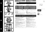
Fig. 3:
Single-channel emer-
gency stop circuit with
earth fault monitoring.
(category 1, up to PL c)
Fig. 2:
Two-channel emergen-
cy stop circuit with earth
fault monitoring.
(category 3, up to PL d)
Fig. 1:
Two-channel emergen-
cy stop circuit with
short circuit and earth
fault monitoring.
(category 4, up to PL e)
Fig. 4:
Two-channel sliding
guard monitoring with
short circuit and earth
fault monitoring.
(category 4, up to PL e)
Emergency Stop
Circuit
Fig. 6:
Monitored manual start
.
It is monitored that the start
button was opened before the
emergency stop button closes.
(Prerequisite: operating voltage
must not be interrupted)
Fig. 7:
Automatic start (e.g. for application with
a safety door).
Max perm. delay during closing of the
safety switches on S12 and S13:
S12 before S13: 300ms;
S13 before S12: any
Warning:
Safety contacts switch
when the power supply is
connected.
Fig. 8:
Feedback loop for monitored manual
start:
The feedback loop monitors contactors
or the expansion modules .
Starting Behavior
Feedback Loop
Note: The items listed under “Electrical connection” must be observed during commissioning.
Commissioning
Procedure
1. Wiring emergency stop circuit:
Wire the emergency stop circuit according to the required
Performance Level determined (see Fig. 1 to Fig 5).
2. Wiring start circuit:
Wire the start circuit according to Fig. 6 or Fig. 7 to set the
starting behavior.
Warning:
If “Automatic start” is set, bear in mind that the safety con-
tacts will switch immediately after the power supply is
connected. If “Monitored manual start” is set, the start
button must be opened after wiring.
3. Wiring feedback loop:
If your application provides for external contactors or ex-
pansion modules, connect them to the device according to
Fig. 8 or Fig. 9.
4. Wiring power supply:
Connect the power supply to terminals A1 and A2 (Fig. 10).
Warning: Wiring only in de-energized state.
5. Set time delay:
Set the desired time delay on the rotary knob
Warning:
Scale divisions should be regarding only as a setting aid.
Always make shure to measure the delay time.
6. Starting the device:
Switch on the operating voltage.
Warning:
If the “Automatic start” starting behavior is set, the safety
contacts will close immediately.
If the “Monitored manual start” starting behavior is set, close
the start button to close the safety contacts.
LEDs K1, K2, K3 and K4 are lit.
7. Triggering safety function:
Open the emergency stop circuit by actuating the connec-
ted safety switch. The safety contacts open immediately.
Warning: Messen Sie die Verzögerungszeit.
8. Reactivation:
Close the emergency stop circuit. If “Automatic start” is
selected, the safety contacts will close immediately.
If the “Monitored manual start” starting behavior is set, close
the start button to close the safety contacts.
Warning:
In order to activate earth fault monitoring, the PE must be
connected only to the power supply unit in accordance with
EN60204-1.
Fig. 5:
Two-channel emergency stop
with pnp-outputs/OSSD-outputs
with short circuit monitoring.
(category 4, up to PL e)
Fig. 9:
Feedback loop for automatic start:
The feedback loop monitors contac-
tors or the expansion modules .
Power supply
and
Safety contacts
Fig. 10:
Power supply A1 and A2.
(Power supply according to techn.
Data )
Fig. 11:
Connecting load to safety contacts.
(Figure shows example.
Voltage „+V“ according to techn.
Data)
SR107AD, SR108AD, SR109AD
User Information for SR107AD, SR108AD, SR109AD


