10355630_V_1_0.DOC
17/28
The device must only be connected with an electric installation carried out in compliance with the IEC-
standards. The electric installation must be equipped with a Residual Current Device (RCD) with a maximum
fault current of 30 mA.
STARTING UP
Make sure to power-up before your power amplifier is turned in order to avoid loud transients which could
damage your speakers or annoy your audience.
System test
After connecting all cables, you should carry out a system test. Press all four Mute-buttons in order to mute
all outputs.
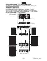
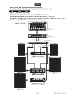
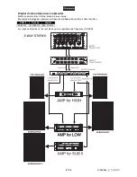
Activate the HF-outputs first. In case of wrong cabling, HF-signals will come out of bass-speakers that cannot
be harmed this way. Vice versa, the LF-signals would destroy your HF-speakers.
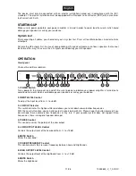
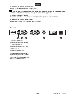
OPERATION
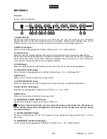
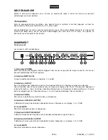
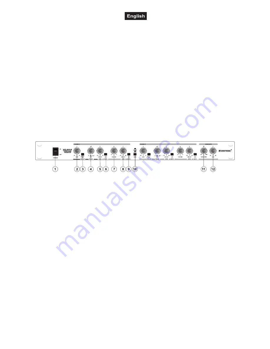
Front panel
Channel A and B are identical.
1. POWER Switch
Turns power to the crossover on and off. Be sure to power-up before your power amplifier is turned on to
avoid loud transients which could damage your speakers or annoy your audience.
2. INPUT LEVEL Control
To adjust the input level from -
∞
to +6 dB.
3. LOW CUT Selector
This switch activates the highpassfilter and allows you to cut down unwanted low frequencies.
With the Low Cut-function, you can attenuate all signals below 30 Hz. Please keep this button pressed if you
do not need these extremely low frequencies at any rate. If your speaker-system does not support these
frequencies, there is danger of speaker damage!
4. PHASE Control
This control reverses the polarity of the Low output.
5. LOW OUTPUT LEVEL Control
Controls the output level of the Low band from -
∞
to +12 dB.
6. MUTE Switch
Mutes the Low band.
7. XOVER FREQUENCY Control
This control adjusts the crossover frequency between Low and High bands.
8. HIGH OUTPUT LEVEL Control
Controls the output level of the High band from -
∞
to +12 dB.
9. MUTE Switch
Mutes the High band.
Содержание XO-23
Страница 2: ......

