background image

00030198.DOC, Version 1.1

18/19

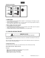
Unbalanced use of
mono 1/4" jack plugs

Tip =
Signal (+)

Sleeve =
Ground / Shield

Tip

Sleeve

Strain relief clamp

Balanced use of

Tip =
hot (+)

Sleeve =
Ground / Shield

Tip

Sleeve

Strain relief clamp

stereo 1/4" jack plugs

Ring =
cold (-)

Ring

For connection of balanced and
unbalanced plugs, ring and sleeve have
to be bridged at the stereo plug.

6.6 Audio connections

7. OPERATION

1.  Prior to switching on turn all controls LEVEL to position “0“ to avoid damage to the hearing by a volume

which is too high when switching on.

2.  Switch the device on via the power switch. The power indicator on the front panel lights up. Switch on

the connected units; always switch on your PA amplifier last.

7.1 Basic setting of the input channels

1.  Set to Master level control to mid position.
2.  Adjust the desired volume ratio with the Level controls. Adjust the channel TONE controls for the desired

balance of lows and highs. The center setting is neutral.

3.  Re-adjust the MASTER LEVEL control to the definitive level of the master signal.

8. CLEANING AND MAINTENANCE

Disconnect from mains before starting maintenance operation!

DANGER TO LIFE!

We recommend a frequent cleaning of the device. Please use a soft lint-free and moistened cloth. Never use
alcohol or solvents!

There are no serviceable parts inside the device except for the fuse. Maintenance and service operations are
only to be carried out by authorized dealers.

8.1 Replacing the fuse

If the fine-wire fuse of the device fuses, only replace the fuse by a fuse of same type and rating.

Before replacing the fuse, unplug mains lead.

Procedure:

Step 1:

 Open the fuseholder on the rear panel with a fitting screwdriver.

Step 2:

 Remove the old fuse from the fuseholder.

Step 3:

 Install the new fuse in the fuseholder.

Step 4:

 Replace the fuseholder in the housing.

Содержание MLM-81

Страница 1: ...interdit Prohibida toda reproducci n F r weiteren Gebrauch aufbewahren Keep this manual for future needs Gardez ce mode d emploi pour des utilisations ult rieures Guarde este manual para posteriores u...

Страница 2: ...herungswechsel 10 9 TECHNISCHE DATEN 11 1 INTRODUCTION 12 2 SAFETY INSTRUCTIONS 12 3 OPERATING DETERMINATIONS 14 4 DESCRIPTION 15 4 1 Features 15 4 2 Front panel 15 4 3 Rear panel 16 5 INSTALLATION 16...

Страница 3: ...00030198 DOC Version 1 1 3 19...

Страница 4: ...ine Mischer MLM 81 entschieden haben Sie haben hiermit ein zuverl ssiges und leistungsstarkes Ger t erworben Wenn Sie nachfolgende Hinweise beachten sind wir sicher dass Sie lange Zeit Freude an Ihrem...

Страница 5: ...le Warnhinweise f r die Netzleitung gelten auch f r evtl Verl ngerungsleitungen Ger t bei Nichtbenutzung und vor jeder Reinigung vom Netz trennen Fassen Sie dazu den Netzstecker an der Griffl che an u...

Страница 6: ...heit Dritter Die Umgebungstemperatur muss zwischen 5 C und 45 C liegen Halten Sie das Ger t von direkter Sonneneinstrahlung auch beim Transport in geschlossenen Wagen und Heizk rpern fern Die relative...

Страница 7: ...e Masterunabh ngiger Durchschleifausgang zum Anschluss eines weiteren MLM 81 Jeder Line Eingang kann intern zu Line Ausgang umkonfiguriert werden 19 Ma e f r Rackeinbau 1 HE Der MLM 81 ist f r den pro...

Страница 8: ...r tes darauf dass die warme Luft aus dem Rack entweichen kann und gen gend Abstand zu anderen Ger ten vorhanden ist Dauerhafte berhitzung kann zu Sch den an dem Ger t f hren Sie k nnen das Ger t mit v...

Страница 9: ...g Verwenden Sie zum parallelen Anschluss eines weiteren MLM 81 den Durchschleifausgang PRE FADE OUT Verbinden Sie den Ausgang des 1 Ger ts mit dem Eingang AUX BUS IN des 2 Ger ts Beachten Sie dass der...

Страница 10: ...ie Mittelposition ist neutral 3 Stellen Sie nun mit dem MASTER LEVEL Regler den endg ltigen Pegel des Mastersignals ein 8 REINIGUNG UND WARTUNG Vor Wartungsarbeiten unbedingt allpolig vom Netz trennen...

Страница 11: ...Verf gung 9 TECHNISCHE DATEN Spannungsversorgung 230 V AC 50 Hz Gesamtanschlusswert 10 W Eingangsimpedanz 600 Ohm Mic 18 kOhm Line 10 kOhm Aux Bus Max Eingangspegel 23 dBV Mic 22 dBV Line Phantomspann...

Страница 12: ...NTRODUCTION Thank you for having chosen the OMNITRONIC Microphone Line Mixer MLM 81 You have acquired a reliable and powerful device If you follow the instructions given in this manual we can assure y...

Страница 13: ...consumption of the device All warnings concerning the power cords are also valid for possible extension cords Always disconnect from the mains when the device is not in use or before cleaning it Only...

Страница 14: ...d consider them Do not shake the device Avoid brute force when installing or operating the device When choosing the installation spot please make sure that the device is not exposed to extreme heat mo...

Страница 15: ...tone controls and signal LEDs Each channel with balanced XLR mic input and unbalanced 6 3 mm 1 4 jack input Each mic input with optional 12 V phantom power via dip switches Master level control master...

Страница 16: ...rear panel The rack should be provided with a cooling fan When mounting the device into the rack please make sure that there is enough space around the device so that the heated air can be passed on...

Страница 17: ...controls are set to minimum position During the stabilization phase approx 1 minute you must not connect or dis connect any mics or adjust output volumes Otherwise danger of speaker damage 6 4 Feed th...

Страница 18: ...d volume ratio with the Level controls Adjust the channel TONE controls for the desired balance of lows and highs The center setting is neutral 3 Re adjust the MASTER LEVEL control to the definitive l...

Страница 19: ...ions please contact your dealer 9 TECHNICAL SPECIFICATIONS Power supply 230 V AC 50 Hz Power consumption 10 W Input impedance 600 Mic 18 k Line 10 k Aux Bus Max input level 23 dBV Mic 22 dBV Line Phan...

Отзывы: