6
Fig. 9
Important
:
DO NOT use a hex wrench on the Re-
taining Nuts (7.2), only apply pressure with your
finger.
Fig. 10
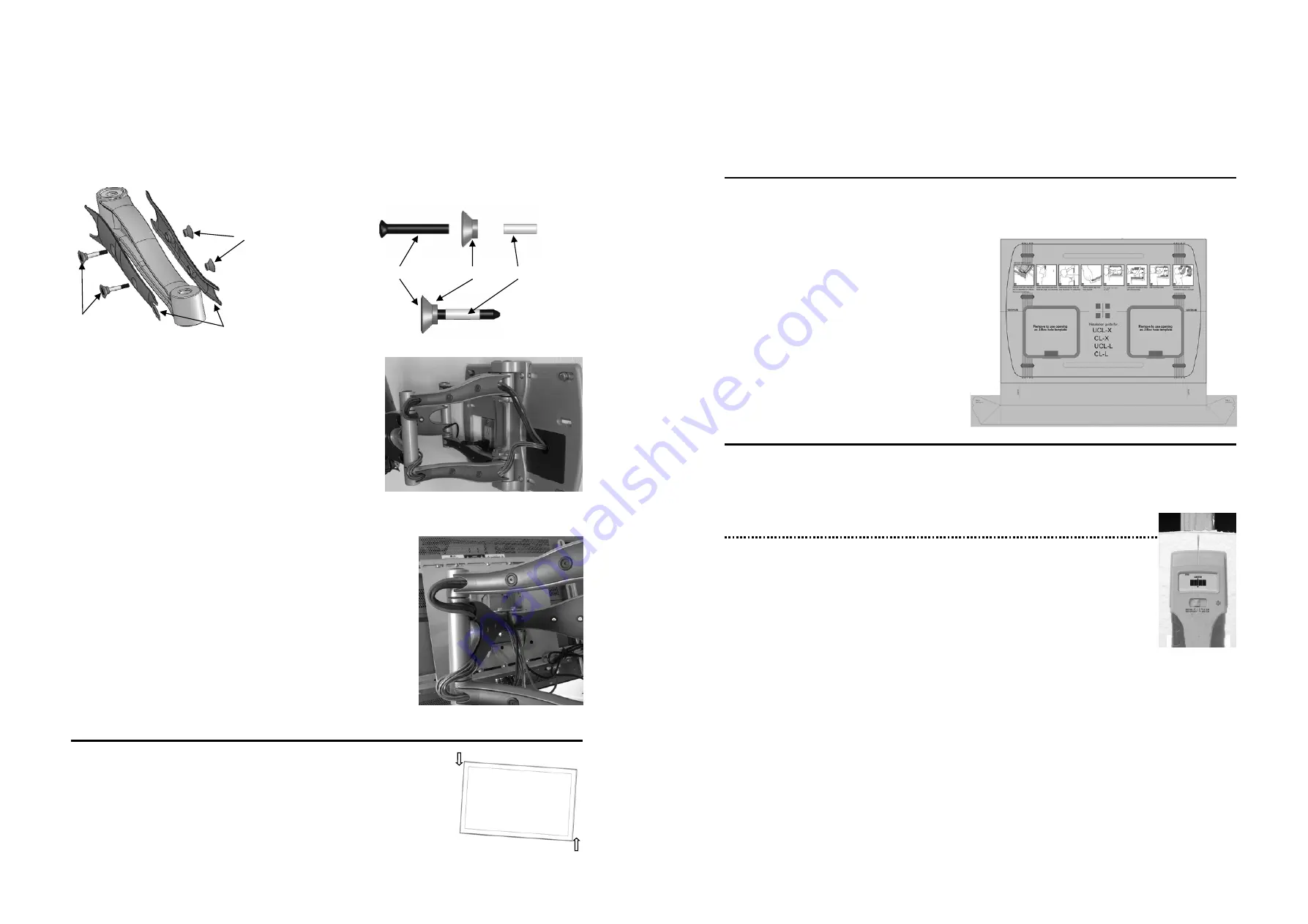
Route the cables along one side of the Inner Arm (nearest the wall
plate), as shown in Fig. 9. With cables in place, loosely secure the Inner
Arm cable covers back in place.
Next, route the cables along the opposite side of the Outer Arm, as shown in
Fig. 10. Be sure to leave slack in the cable where it transitions between the
two sides of the Arm Assembly. With cables in position, loosely secure the
Outer Arm cable covers back in place.
Note: For best system performance, route the AC
power cable separately from the signal cables.
With all cables in place, pull the display in and out and check that the arm
assembly moves freely, without stretching or damaging the cables, and then
secure the cable covers.
Step 7 — Using Cable Management
The Wishbone series cantilevers include a cable management function, where cables can be routed along the length of the
arm assembly.
To install cables, you’ll first need to remove the cable covers. Using a Phillips Head screwdriver on the Retaining Screw
(7.1) and pushing on the Retaining Nuts (7.2) with your finger, remove the screw assembly (Fig. 8). Remove the Cable
Covers (7.3) and set all parts aside.
Fig. 7
7.2
7.1
7.3
Retaining Screw
Fig. 8:
Screw Assembly
Cover Washer
Plastic Sleeve
Step 8 — Adjusting the Display
The Wishbone series cantilevers provide a wealth of flat panel display adjustment to
offer the best viewing from a number of seating positions.
Roll Control
—
Horizontal leveling of the flat panel display.
Grasp the edge of the display and roll it up or down into a level position. (Fig 11)
Fig. 11
3
Step 1 — Determine the Mounting Location
To provide maximum viewing flexibility, the OmniMount Wishbone Series cantilever mounts are capable of a wide range
of motion, which allows the flat panel display to be positioned for viewing from many different angles.
When selecting the mounting location for the display, make sure there is adequate space on all sides of the display, consid-
ering the dimensions (H x W) of your particular flat panel display model.
Step 2 — The Installation Template
The Installation Template is designed to make the installation of the wall plate faster, easier and more accurate. In addi-
tion, the template can be used to locate and mount any
required electrical boxes for routing AC power and A/V
signals to the display. Finally, the template includes a
built in dust channel to reduce the clean up chores from
mounting the CL-X.
Assembling the Dust Channel:
Locate the supplied mounting template. (Fig. 1)
Fold the dust collector along the marked lines:
a. Fold main channel up.
b. Crease and fold the tab sections inward.
c.
Fold outer portion of tab around the back
of the guide, and then insert tab into slot.
Step 3 — Mounting to the Wall
Follow the instructions based upon your mounting surface:
3a Wooden
Stud
3b Concrete/Masonry
3c Cinder
Block
Step 3a — Mounting to Wooden Studs
The CL-X can be mounted onto two wooden studs, with center to center distances between 15” and
17” (38—43 cm).
Using an electronic stud finder (Fig 2), locate the center of the two wooden studs at the desired mount-
ing location. Mark the stud center positions directly onto the wall. Extend the stud center lines, and
then draw a horizontal line between the studs to represent where you wish the center of the screen to be
located. Measure and mark the center of this horizontal line.
Insert supplied thumbtack into center cross-hair on template, and then remove the tape strip from the back of the tem-
plate. Pin the template to the center mark on the wall. Using a level (bubble or laser), level the guide, and then press the
adhesive backing against the wall to hold the guide in place.
Note: Depending upon the roughness of the surface, you may need to hold the template in place with an application of
blue painters tape.
Using a 1/4” (6 mm) drill bit, drill 6 pilot holes into the center of the studs (through the mounting hole cut-out sections of
the template), down to a depth of 3” (76 mm).
Note: For best results from the dust channel, press and hold the template against the wall about 2” (50 mm) from where
you are drilling.
If installing electrical boxes for an AC outlet and/or A/V signal cables, carefully remove the perforated sections of the
guide and then mark the wallboard. This mark will define the area in which electrical boxes may be installed.
Carefully remove the guide from the wall, and discard. Note: Be sure to hold the guide in an upright position so as not to
spill the collected dust.
Fig. 2
Fig. 1


