background image

RU

14

Электронная версия

Подключение к тахометру

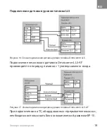
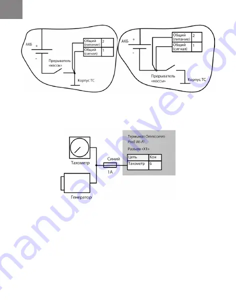
Рисунок 5. Схема подключения на ТС 

после прерывателя «массы» 

Рисунок 6. Схема подключения на ТС  

до прерывателя «массы»  

Рисунок 7. Схема подключения к тахометру

Содержание Profi Wi-Fi 3.0

Страница 1: ...800 100 24 42 7 495 989 62 20 info omnicomm ru www omnicomm ru Passport Made in Russia Omnicomm 68 70 Building 1 Butyrski Val str 127055 Moscow Russia 7 495 108 04 23 support omnicomm world com www om...

Страница 2: ...RU 1 2 3 7 8 8 21 21 22 22...

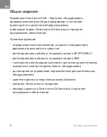
Страница 3: ...RU 2 Omnicomm Profi Omnicomm Online GPS GSM Omnicomm Online...

Страница 4: ...RU 3 1 100 5x137 0x38 0 2 SIM SIM SIM SIM chip IP54 14254 96 Omnicomm EGTS 0 28 52230 2004 8 8 65 1400 Li pol 1 3 1 2 0...

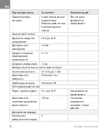
Страница 5: ...RU 4 6 0 14 12 0 5 20240 350 1 240 150 000 8 g GPS GSM GSM GPRS 850 900 1800 1900 Wi Fi IEEE 802 11 b g n...

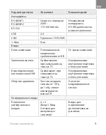
Страница 6: ...RU 5 RS 485 1 2400 115 200 RS 485 RS 485 2 RS 232 USB 2 0 CAN J1939 FMS 1 Wire 8 GSM 10 1 5 4 2 5 6...

Страница 7: ...RU 6 0 30 12 1 1 10 1 1 5 1 30 100 2...

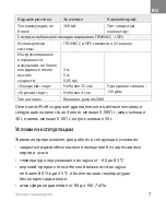
Страница 8: ...RU 7 300 GPS GPS 32 3 5 0 05 35 130 4 SMA Omnicomm Profi c 0 0001 30 0 001 30 40 85 80 35 84 106 7...

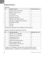
Страница 9: ...RU 8 2 1 Omnicomm Profi 1 2 GPS 1 3 Wi Fi 1 4 1 5 1 6 1 7 1 8 1 9 1 10 1 3 1 3 5 13 DIN 7981 4 2 3 5 32 DIN 7981 2 3 1 2 4 3 1 5 3 6 6 7 150 2 5 3 8 3...

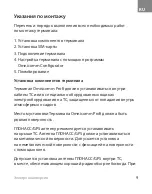
Страница 10: ...RU 9 1 2 SIM 3 4 Omnicomm Configurator 5 Omnicomm Profi Omnicomm Profi GPS GPS GPS...

Страница 11: ...RU 10 GPS GPS Wi Fi SIM SIM PIN PIN SIM SIM SIM SIM SIM...

Страница 12: ...RU 11 4 1 1 2 3 4 2 2 5 4 4 6 7 2 2 8 RX RS 232 RS 232 RX 9 B RS 485 2 B RS 485 2 10 B RS 485 1 B RS 485 1 11 CAN L CAN L 12 13 IGN 14 GSM GSM 15 1 1 16 3 3...

Страница 13: ...RU 12 17 Ibutton Ibutton 18 1 1 19 TX RS 232 RS 232 TX 20 A RS 485 2 RS 485 2 A 21 A RS 485 1 A RS 485 1 22 CAN CAN 5 2 1 2 3 4 5 5 5 6 7 8 Ibutton Ibutton 9 6 6 10 LLS PWR LLS...

Страница 14: ...RU 13 1 Omnicomm Profi 2 1 3 2 4...

Страница 15: ...RU 14 5 6 7...

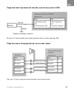
Страница 16: ...RU 15 GSM 8 GSM 9...

Страница 17: ...RU 16 RS 232 RS 485 10 11 11 RS 485 10 RS 232...

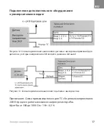
Страница 18: ...RU 17 24 R R 500 1000 1 0 5 12 24 13...

Страница 19: ...RU 18 N P N 14 N P N 15...

Страница 20: ...RU 19 LLS Omnicomm LLS AF 1 15 16 Omnicomm LLS 17 Omnicomm LLS AF...

Страница 21: ...RU 20 12 24 18 Omnicomm LLS 20230 20240 19...

Страница 22: ...RU 21 Omnicomm Configurator 25 70 50 35 5 Omnicomm Profi 1 15150 2 15150 6...

Страница 23: ...RU 22 Omnicomm Profi 127055 68 70 1 8 800 100 24 42 7 495 989 62 20 info omnicomm ru 1 1 3...

Страница 24: ...RU 23 Omnicomm Profi 29 32 30 160 024 03066711 2018...

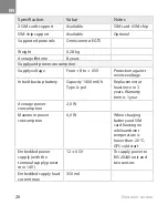
Страница 25: ...24 Electronic version Contents 25 General information 25 Technical specifications 30 Operating conditions 30 Supply set 31 Assembly instructions 43 Transportation and storage 43 Omnicomm limited warra...

Страница 26: ...jamming detection Active GSM jamming detection Reading fuel level sensors and wide range of the connected equipment as well as filtering the obtained data Remote control of the connected auxiliary eq...

Страница 27: ...ction against reverse voltage Inbuilt backup battery Capacity 1400 m h Type Li pol Replacement at least once in 3 years Warranty term is 1 year Average power consumption 2 0 W Maximum power consumptio...

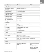
Страница 28: ...ming detector Available GSM jamming detector Available Interfaces USB 2 0 CAN J1939 FMS RS 485 1 Transmission rate from 2 400 to 115 200 bit sec RS 485 2 RS 232 1 Wire Available Data transfer channel...

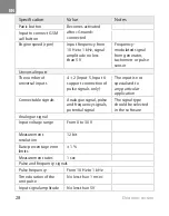
Страница 29: ...2 Input 5 Input 6 support connection of pulse signals only The input is not specialized to any particular application Connectable signals Analogue signal pulse and frequency signals potential signal T...

Страница 30: ...open collector type Global Positioning System GLONASS GPS Systems utilized GLONASS and GPS jointly 32 channels Margin of the maximum permissible instrumental error in measuring the coordinates in the...

Страница 31: ...at lower temperatures without moisture condensation atmospheric pressure from 84 to 106 7 kPa Supply set Table 2 Description Quantity pcs 1 Omnicomm Profi Terminal 1 2 GLONASS GPS antenna 1 3 Wi Fi an...

Страница 32: ...list of necessary steps to install the device 1 Installing Omnicomm Profi Terminal s component parts 2 Inserting SIM cards 3 Connecting Omnicomm Profi Terminal 4 Configuring Omnicomm Profi Terminal w...

Страница 33: ...ou must only place it on a horizontal surface in so doing please do not forget to check the quality of GLONASS GPS signal reception The best places to install the Wi Fi antenna is the VH windshield or...

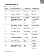
Страница 34: ...of wire in the cable 1 Ground for power supply Ground supply White 2 Ground for power supply Ground supply White 3 Panic button Panic button White Red 4 Universal input 2 Input 2 Black White 5 Univers...

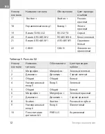
Страница 35: ...e 22 CAN CAN Violet Orange Table 5 Connector 2 No of the contact Name of the signal Designation Color of wire in the cable 1 Microphone Microphone Green Yellow 2 Speaker Speaker Grey Yellow 3 Ground f...

Страница 36: ...cting to the supply circuit and the ignition key In VHs which are not equipped with the ground switch the device should be connected to the supply circuit and the ignition key as shown on the scheme F...

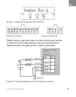
Страница 37: ...eme of connection to the supply circuit when it takes place behind the ground switch Figure 6 Scheme of connection to the VH supply circuit when it takes place ahead of the ground switch Figure 7 Sche...

Страница 38: ...the Panic button and the GSM call button Connecting the voice communication equipment Figure 8 Scheme of connecting both Panic button and GSM call button Figure 9 Connector pin array required to conne...

Страница 39: ...EN 38 Electronic version Connecting the auxiliary equipment to the RS 232 and RS 485 interfaces Figure 10 Figure 11...

Страница 40: ...unified voltage output for the sensors in which the voltage of 24 V falls within the power supply range to the universal input of the Omnicomm Profi Terminal Figure 13 Connection scheme for the analog...

Страница 41: ...eme of connection of the sensor which has a N P N output of open collector type to the universal input of the Omnicomm Profi Terminal Figure 15 Scheme of connection of a contact sensor to the universa...

Страница 42: ...performed according to the scheme Omnicomm LLS AF sensors must be connected in order starting from the 1st universal input Figure 16 Scheme of connection of the LLS fuel level sensor to the Omnicomm...

Страница 43: ...equipment should be performed using the addition relay according to the scheme Figure 18 Scheme of connection of the Omnicomm LLS 20230 fuel level sensor to the Omnicomm Profi Terminal if being conne...

Страница 44: ...s following the date of manufacture Omnicomm limited warranty OMNICOMM warrants that this product under normal use and conditions will be free from defects in materials and workmanship for a period of...

Страница 45: ...isted documents are not presented or if the information they contain is incomplete or illegible this warranty shall not apply if the model name or serial number of the product has been altered erased...

Страница 46: ...tem or mechanical parts In addition this warranty shall not cover components expected to require periodic replacements during product life cycle such as batteries cables et cetera or installation usag...

Страница 47: ...e remedy for claims related to or arising out the these terms and conditions for any legal cause and despite the form of action whether in contract or in tort statutory or otherwise including negligen...

Страница 48: ...26 07 2021 EDITION 10R05 01 2727 00...

Отзывы: