


A
A
AUDIO COnfIgUrAtIOn
InItIAL SEt UP & AUDIO COnnECtIOnS
AUDIO COnnECtIOnS
(COnt.)
rACK MOUntIng
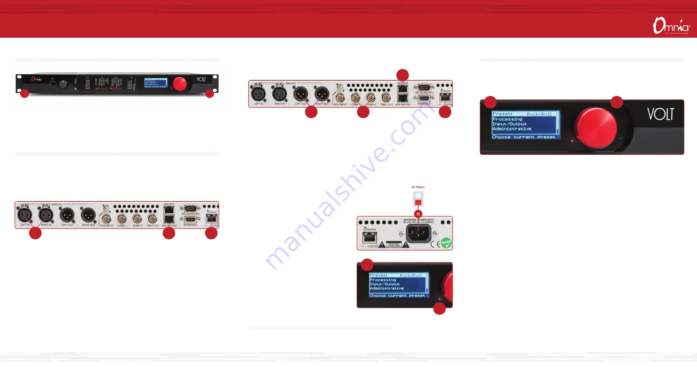
1. Install the VOLT in your equipment rack using the 4 supplied screws. If only two screws are used
for installation, they MUST be installed in the bottom holes (A) of the rack ears. As a best practice,
leave a blank space above and below the unit for proper ventilation and cooling.
a. For balanced line-level analog audio, connect XLR audio cables to the ANALOG LEFT IN and RIGHT IN
jacks (B).
b. For AES digital audio, connect the dual female XLR “Studio Hub” adaptor cable provided to the
RJ-45 AES IN/SYNC jack (C).
c. For an existing Axia or Livewire system, connect an Ethernet cable from the Livewire network to the
Livewire jack (D).
AUDIO COnnECtIOnS
1. Determine the inputs and outputs that are appropriate for your installation.
AUDIO INPUT - Both analog and digital input sources may be connected simultaneously,
however, only the input source that has been selected in the Input menu will be active.
B
C
D
a. For balanced line-level analog, connect XLR audio cables to the ANALOG LEFT OUT and RIGHT OUT
jacks (E).
b. For Digital audio, connect the male XLR “Studio Hub” adaptor cable provided to the RJ-45 AES OUT jack (F).
c. For an existing Axia or Livewire system, the single Livewire Ethernet connection made in the input setup
is all that is needed for audio I/O (D).
d. If using the built-in FM stereo generator, connect one of the composite MPX BNC outputs (G) to your FM
exciter or composite STL.
AUDIO OUTPUT - All outputs are active simultaneously.
E
F
D
G
COntInUE tO AUDIO COnfIgUrAtIOn
The initial set-up of your Omnia VOLT is complete and ready to be configured.
Continue to the "Audio Configuration" instructions.
J
I
InPUt COnfIgUrAtIOn
The Omnia VOLT can be set up and customized for your station’s sound directly from the front panel. Note that all
of front panel functions, and more, can also be accessed via password protected login from networked computers,
tablets or smartphones. For instructions on how to configure via networked devices, please refer to the Remote
Control chapter in the Omnia VOLT manual.
J
K
1. Navigating input configuration on the front panel is simple and intuitive. Rotate the red jog wheel (K) to scroll
through options displayed on the LCD screen (J), increase/decrease numeric options and more. Press the jog
wheel (K) to make a navigation selection or to enter settings.
2. From the front LCD screen, rotate the red Jog wheel until Input/Output is highlighted. Press the jog wheel in
to select.
3. Rotate the jog wheel until Input is highlighted. Press to select.
4. Rotate the jog wheel until Input Src is highlighted. Press to select.
5. Rotate the jog wheel to select the appropriate input source. Press to select.
6. Feed regular program material at your station’s normal level (usually 0 VU on the console meters).
Adjust VOLT’s appropriate Level control so it’s input LEDs bounce up to about -16 to -12 dB on peaks.
Press the jog wheel to accept the setting.
7. Rotate the jog wheel until Exit is highlighted. Press to return to the Input/Output menu screen.
2. Connect the Omnia VOLT to AC Mains (H) using
the AC power cable supplied. Make sure the power
source is properly grounded. There is no power
switch.
3. Once power is supplied, a red power indicator (I)
next to the LCD (J) will light up. The LCD will remain
dark for about 25 seconds, then will display “Omnia
VOLT”as the startup sequence progresses. A few
seconds later, the main menu will be displayed.


