


22
Yellow/Black Wire:
Connection
Required
The Yellow/Black wire must be connected. It is part a critical safety feature
which disables the RS unit whenever the brake pedal is pressed.
Connect the Yellow/Black wire to the brake switch wire which shows 12 Volts
when the brake pedal is pressed. The brake switch is typically located above the
brake pedal, and usually mounted to the brake pedal support bracket. Always
make this connection in a fashion ensuring its long-term reliability; soldering is
highly recommended. Upon completing the Yellow/Black wire's connection, thor-
oughly test the operation of this circuit.
Pink Wire:
Connection If Desired
The Pink wire activates the RS Unit. If the Pink wire receives a Negative
pulse, the RS unit will start the vehicle's engine, provided that all safety circuits are
in the proper status. After the engine has been started by remote control, another
Negative pulse on the Pink wire will turn the RS unit off, stopping the engine.
The Pink wire can be connected to an available auxiliary output of an existing
Remote Security System, or the RS-7K's remote control may be used to activate
the unit.
23
Gray Wire:
Connection If Desired
The function of the Gray wire is to provide a Negative 500ma auxiliary output
which may be used to operate a trunk release or other interface.
Trunk Release Connection:
1) Connect the Gray wire to pin
#
85 of the external relay.
2) Connect Constant 12 Volts to pin
#
86 of the external relay. (Fused)
3) Connect pins
#
87, 87a & 30 as indicated in diagram
#
10 on page 24.
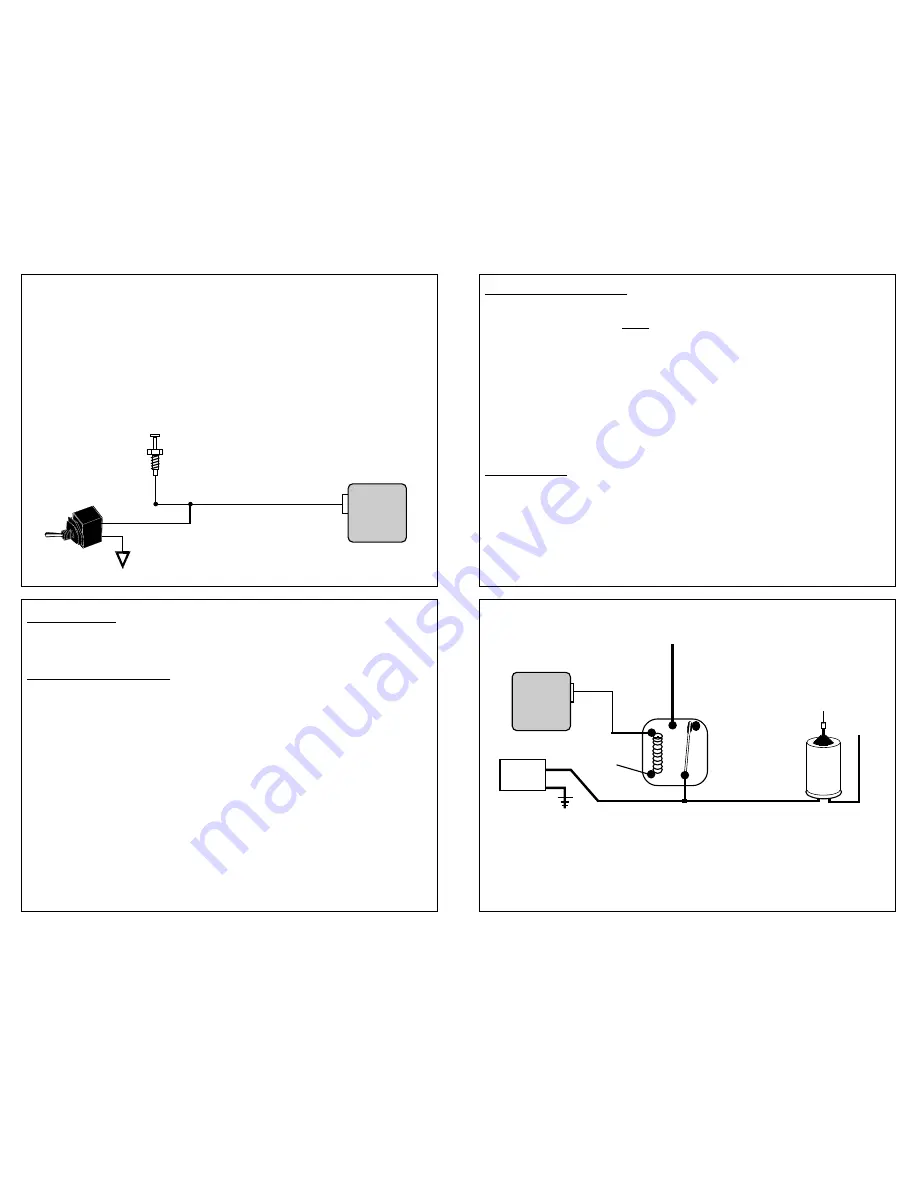
24
Connect to 12 Volts or Negative Ground as needed in the
particular application. (In this case Negative is required)
Note: In some applications the solenoid wire will rest at ground. In these cases:
- Cut the solenoid wire:
- Connect the switch side to pin
#
87a of the external relay.
- Connect the solenoid side to pin
#
30 of the external relay.
- Connect 12 Volts to pin
#
87 of the external relay (Fused).
Diagram
#
10
85
86
87a
87
Coil
30
Trunk
Switch
Gray Wire
12 Volts
Relay
Release
Solenoid
Control
Module
21
Remote Start Override Mode:
The RS unit can be placed into an "Override" mode which will prevent it from start-
ing the vehicle. This mode is for situations when it is not convenient or safe for the
Remote Start feature to be operable. For example during extended stopovers for
vehicle servicing, maintenance, valet parking, washing, etc.
Connect the Dark Blue wire to one of the included toggle switch's two wires. Con-
nect the toggle switch's remaining wire to ground.
Hood
Pin
Switch
Dark Blue Wire
Diagram
#
9
Ground
Control
Module


