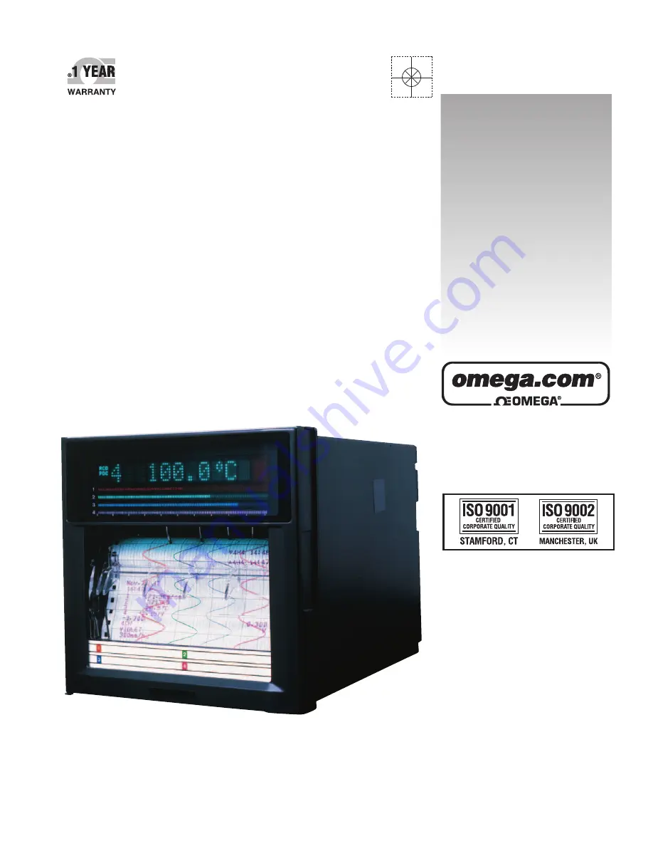
manualshive.com logo in svg
background image

RD100B

Programmable Recorder

omega.com  

e-mail: [email protected]

For latest product manuals:

omegamanual.info

Shop online at

User’s Guide


Содержание RD100B

Страница 1: ...RD100B Programmable Recorder omega com e mail info omega com For latest product manuals omegamanual info Shop online at User sGuide...

Страница 2: ...e TEL 33 0 1 61 37 2900 FAX 33 0 1 30 57 5427 Toll Free in France 0800 466 342 e mail sales omega fr Germany Austria Daimlerstrasse 26 D 75392 Deckenpfronn Germany TEL 49 0 7056 9398 0 FAX 49 0 7056 9...

Страница 3: ...a result of continuing improvements to the instrument s performance and functions Every effort has been made in the preparation of this manual to ensure the accuracy of its contents However should yo...

Страница 4: ...h the nth day of the week of that month and time Added Modbus slave protocol Two wire system Changed Users with the same user name cannot be registered Checking the Version Number You can check the ve...

Страница 5: ...manual Protective ground terminal AC High temperature To avoid injury caused by hot surface do not touch locations where this symbol appears For the protection and safe use of the product and the sys...

Страница 6: ...ct the protective grounding before connecting to the item under measurement or to an external control unit Damage to the Protective Structure Operating the recorder in a manner not described in this m...

Страница 7: ...r RD100B 3 pen recorder RD100B 4 pen recorder RD100B 6 dot recorder Japanese English deg F DST RD101B RD102B RD103B RD104B RD106B 1 A1 A2 and A3 cannot be specified simultaneously 2 A3 and F1 cannot b...

Страница 8: ...er make sure that all contents are present and undamaged For information about ordering accessories contact the dealer from which you purchased the recorder Red Green Blue Violet Purple Disposable fel...

Страница 9: ...he tab at the lower left of the display and open the display Display Tab on the display Open Open Remove all packing materials Pen Model Hinge Dot Model Hinge CAUTION To protect the hinges do not appl...

Страница 10: ...s how to assign tags to channels and how to set message strings that are to be printed 7 Setup Operations for Changing Adding Functions Basic Setting Mode Describes the setup operations for changing o...

Страница 11: ...rrences CAUTION Calls attentions to actions or conditions that could cause light injury to the user or damage to the instrument or user s data and precautions that can be taken to prevent such occurre...

Страница 12: ...3 1 Names of Parts 3 1 3 2 Installing or Replacing the Chart Paper 3 4 3 3 Installing Replacing Felt Pens or Plotter Pen Pen Model 3 7 3 4 Installing Replacing the Ribbon Cassette Dot Model 3 9 3 5 S...

Страница 13: ...r Dot Model 7 8 7 6 Recording by Compensating for the Pen Offset along the Time Axis Pen Model 7 9 7 7 Turning Printouts ON OFF 7 10 7 8 Setting the Periodic Printout Interval and the Type of Measured...

Страница 14: ...9 28 Chapter 10 Troubleshooting 10 1 A List of Error Messages 10 1 10 2 Troubleshooting Flow Charts 10 4 Chapter 11 Maintenance 11 1 Periodic Inspection 11 1 11 2 Cleaning the Recorder 11 2 11 3 Repla...

Страница 15: ...ngs can be printed Internal Light A light is provided for easier viewing of the recording area of the chart paper Display Measured values can be displayed numerically or using bar graphs on the large...

Страница 16: ...nction input less than 0 is fixed to 0 scale left value can be used Current Input A shunt resistor is attached to the input terminal The current signal is converted to a voltage signal and measured Th...

Страница 17: ...mputation cannot be designated Scaling The input values are scaled to values in the appropriate unit to be used as measured values 0 V 100 0 C 10 V 300 0 C Measured value Input value Square Root Compu...

Страница 18: ...re using a thermocouple the reference junction compensation on the recorder can be used When using external reference junction compensation you can set the reference voltage The reference junction com...

Страница 19: ...or a step input Moving Average Dot Model The average value of the m most recent values acquired at the scan interval is used as the measured value of the channel The number of moving averaged data poi...

Страница 20: ...odel Integration Time of the A D Converter Pen model Select 16 7 ms 60 Hz 20 ms 50 Hz or Auto Dot model Select 16 7 ms 60 Hz 20 ms 50 Hz 100 ms or Auto If Auto is selected the recorder detects the pow...

Страница 21: ...ified value Difference Low Limit Alarm l An alarm occurs when the difference in the input values of two channels is less than or equal to the specified value Can be specified on channels set to delta...

Страница 22: ...m is released Note The alarm detection operation is reset when a power failure occurs The operation restarts after the power recovers If the alarm value is changed while a delay alarm is occurring the...

Страница 23: ...e section 1 4 Alarm Output Relay A1 A2 and A3 Options Contact signals can be generated from alarm output relays when alarms occur The number of output relays is 2 A1 4 A2 or 6 A3 The alarm output rela...

Страница 24: ...he reflash alarm is disabled Alarm Alarm output relay Reflash alarm ON Alarm output relay Reflash alarm OFF Channel 1 Channel 3 Channel 2 Approx 500 ms Approx 500 ms Note If the reflash alarm is enabl...

Страница 25: ...is enabled I01 is set to diagnosis output Specifying AND produces no effect Related Topics Setting the AND operation Section 7 1 Energized De energized Operation of Alarm Output Relays You can select...

Страница 26: ...ivated Released Note If the reflash alarm is enabled I01 to I03 are fixed to non hold operation Specifying Hold produces no effect If diagnosis output is enabled I01 is fixed to non hold operation Spe...

Страница 27: ...as well as various other types of information Recording Example on the Pen Model Recording Example on the Dot Model The recording examples may appear differently from the actual recording as a result...

Страница 28: ...rinting interval at all times The recording colors in order from channel 01 are purple red green blue brown and black The recording color of each channel can be changed among these six colors For each...

Страница 29: ...are offsets along the time axis phase difference between the pens This offset is corrected when pen offset compensation is used Same time Below is an explanation for the 2 pen model The recording of...

Страница 30: ...T 205 ABCDEF 1H3 10 09 1H3 10 05 Nov 09 04 13 50 1 218 7mg cm3 2 390 6 S cm 3 H 598 4 C 4 d 0 222V 0 0 500 0 1CH mg cm3 RED 50mm h_ Time tick The time ticks are marks that indicate the positions of th...

Страница 31: ...2 437 2 S cm 3 H 591 6 C 4 0 222V 5 0 665V 6 L 0 448V _50mm h 14 55 _08 00 25mm h 09 52 START 205 ABCDEF 1H3 10 09 1H3 10 05 Nov 09 04 13 50 1 218 7mg cm3 2 390 6 S cm 3 H 598 4 C 4 d 0 222V 5 0 995V...

Страница 32: ...nts for details see appendix 1 Date time time ticks marks that indicate the positions of the date time on the chart paper measured values alarm status scale leftmost and rightmost values of span and r...

Страница 33: ...ffer is full the message is not printed A buffer overflow mark is printed when there are messages that cannot be printed because the buffer is full The time printout format can be selected New Chart S...

Страница 34: ...uch as the input range and alarm for each channel Setup List contains settings of basic specifications such as the alarm output relay operation and printout method Printout Example of List on the Pen...

Страница 35: ...tion 1 Printout Example of List on the Dot Model The printout examples may appear differently from the actual printout as a result of functional improvements made on the recorder after this manual was...

Страница 36: ...is released If the alarm indication is set to hold operation the indicator blinks when an alarm occurs When alarm ACK operation is performed the indicator turns ON or OFF MATH This indicator turns ON...

Страница 37: ...n channel Channel on which an alarm is occurring Channel on which an alarm is not occurring Channel on which an alarm is not set Date Time and Chart Speed The date format can be specified Date Chart s...

Страница 38: ...ponent EXP Determines the exponent y ex Relational computation LT LE GT GE Determines or of two elements and outputs 0 or 1 EQ NE Logical computation AND OR XOR NOT Determines the AND logical product...

Страница 39: ...value of channel 02 is 20 V the computed result of 01 02 is 40 Recording Computation Channels Trend Recording Trend recording is possible by setting the recording span for each computation channel The...

Страница 40: ...Topics Setting the periodic printout Section 7 8 9 6 and 9 15 Setting the printout using the TLOG timer Section 9 6 and 9 12 Alarms Up to 4 alarms can be assigned to each computation channel The alar...

Страница 41: ...the power is turned OFF including a power failure This relay behavior cannot be changed FAIL Relay Output NO C NC Normal NO C NC Failure NO C NC Power OFF NO Normally Opened C Common NC Normally Clos...

Страница 42: ...s applied to the terminal The secondary chart speed is set in advance Message 1 Printout to Message 5 Printout Remote input signal Trigger Prints message 1 to 5 on the chart paper Manual Printout Remo...

Страница 43: ...uces no effect Remote Signal Edge Trigger and Level The above actions are carried out on the rising or falling edge of the remote signal edge the ON signal lasting at least 250 ms trigger or the ON OF...

Страница 44: ...cement pen model ribbon cassette replacement dot model Related Topics Setting the key lock function Section 7 10 Using the key lock function Section 3 13 Language The display and recording language ca...

Страница 45: ...deformation Keep electrically charged objects away from the recorder as this may cause malfunction Do not apply volatile chemicals to the door glass display panel keys etc Do not allow rubber and vin...

Страница 46: ...ting Note Condensation may occur if the recorder is moved to another place where both the ambient temperature and humidity are higher or if the temperature changes rapidly In addition measurement erro...

Страница 47: ...he panel according to the procedure below First attach the two mounting brackets and temporarily fasten the attachment screws Next fix the recorder in place by tightening the attachment screws with th...

Страница 48: ...nel Cutout 137 5 39 2 0 137 5 39 2 0 137 5 39 2 0 137 5 39 2 0 L 2 0 L 2 0 L mm Side by Side Mounting vertically max 3 units Side by Side Mounting horizontally Units Single Unit Mounting 175 min 6 89...

Страница 49: ...with insulation sleeves designed for 4 mm screws be used when connecting the input output signal wires to the terminals However this does not apply clamped terminals H2 Crimp on lug with insulation sl...

Страница 50: ...devices If you need to make a parallel connection then Turn the burnout detection function OFF Ground the instruments to the same point Do not turn ON or OFF another instrument during operation This...

Страница 51: ...s Clamped input terminal Screw input terminal Philips screwdriver Flat blade screwdriver Crimp on lug with insulation sleeves Signal wire Signal wire Note Input signal wires of diameter less than or e...

Страница 52: ...input Leadwire resistance 10 max wire The resistance of the three wires should be equal Example For a 4 to 20 mA input a shunt resistor of 250 0 1 can be used to convert to 1 5V input A B b Note RTD...

Страница 53: ...ot to touch the terminals Crimp on lug with insulation sleeves for 4 mm screws CAUTION To prevent fire use signal wires having a temperature rating of 70 C or more If a strong tension is applied to th...

Страница 54: ...R1 R1 F1 NO C NC NO C NC NO C NC NO C NC NO C NC NO C NC A3 NO C NC NO C NC NO C NC NO C NC NO C NC NO C NC A3 R1 F1 I01 I02 I03 I04 I05 I06 I01 I02 I03 I04 I05 I06 NO C NC NO C NC R1 CE FAIL 1 2 3 4...

Страница 55: ...wiring of the remote control input terminals Connect the shield to the ground terminal of the recorder Relay Contact Output Specifications Output type Relay Contact rating 250 VAC 50 60 Hz 3 A 250 VDC...

Страница 56: ...e type on the power supply line in order to separate the recorder from the main power supply Put an indication on this switch as the breaker on the power supply line for the recorder and indications o...

Страница 57: ...minal cover in place Power terminal block Power terminal cover Open 2 Wire the power cord and the protective ground cord to the power supply terminals Use ring tongue crimp on lugs designed for 4 mm s...

Страница 58: ...of the recorder or another device during operation This can have adverse effects on the measured values If nothing is displayed when the power switch is turned ON turn OFF the power switch and check t...

Страница 59: ...ounting hole There is one hole on each of the top bottom left and right panels The hole is covered with a seal Pen model Dot model Display and key panel see the next page There is an internal light on...

Страница 60: ...ches the setup item or the value Press this key while holding down the SHIFT key to switch the setup item or the value in reverse order LEFT RIGHT Key Moves the cursor to the right when entering a val...

Страница 61: ...minals Heatsink Dissipates the internal heat Optional terminal block This is where terminals or ports used by options such as alarm output relays and communication interface are installed Ethernet por...

Страница 62: ...t cassette platen the cylindrical section that holds the paper during the recording operation Be sure to replace the chart paper ahead of time Loading the Chart Paper 1 Open the door If recording is i...

Страница 63: ...d the chart paper Riffle the chart thoroughly before loading Make sure that the sprocket teeth of the chart drives are properly engaged in the chart paper perforations Make sure not to load the chart...

Страница 64: ...order and press the entire chart cassette into the recorder case The chart cassette is fixed in place with the stoppers Stopper Feeding the Chart Paper 7 Press the FEED key to assure that the chart mo...

Страница 65: ...y change its color Replacing Felt Pens 1 Open the door If recording is in progress press the RCD key to stop the recording 2 Open the display and key panel section You can open the display and key pan...

Страница 66: ...older moves near the center position and the Pen exchange End appears Note When the pen moves a line is drawn on the chart paper 4 Replace the pen 5 Press the CH UP key The screen returns to the data...

Страница 67: ...3 Press the DISP key several times to display R exchange Func R exchange 4 Press the CH UP key The printer carriage moves near the center position and R exchange End is displayed 5 Open the display an...

Страница 68: ...he cassette with the ribbon feeding shaft hole of the holder Holder tab Hole for the ribbon feed shaft Cassette holder Ribbon feeding knob 8 Turn the ribbon feeding knob in the direction of the arrow...

Страница 69: ...rd RECORD Stopping the Recording While recording is in progress press the RCD key to stop recording The word RECORD on the status display clears Feeding the Chart Paper The chart paper is fed while th...

Страница 70: ...ues the displayed channel is automatically switched in ascending order The switching interval can be set to 1 s 2 s 3 s 4 s or 5 s Measurement channels set to Skip and computation channels set to OFF...

Страница 71: ...der continues the measurement and alarm detection in the background When manual printout is complete trend recording resumes If an alarm occurs during the manual printout the alarm is printed after th...

Страница 72: ...and then press the key The List printout starts The screen returns to the data display screen Print List Start Aborting the List Printout 1 Press the FUNC key 2 Press the key to select Print out and t...

Страница 73: ...nt unneeded alarm printouts from being executed Procedure 1 Press the FUNC key 2 Press the key to select Buffer clear and then press the key Func Buffer clear 3 Press the key to select Alarm and then...

Страница 74: ...select Message and then press the key Func Message 3 Press the key to select message number and then press the key The message printout starts The screen returns to the data display screen Displays th...

Страница 75: ...ntout Procedure Resetting the Report Data 1 Press the FUNC key 2 Press the key to select Periodic and then press the key Func Periodic 3 Press the key to select Reset and then press the key The report...

Страница 76: ...eleased The alarm output is released when the alarm ACK operation is carried out When an alarm is occurring The alarm output is held even after the alarm ACK operation If the alarm ACK operation is ca...

Страница 77: ...and then press the key The key lock is activated The screen returns to the data display screen Func Keylock Releasing the Key Lock Note A password is required to release the key lock 1 Press the FUNC...

Страница 78: ...hannels cannot be changed while computation M1 option is in progress The operations that can be carried out in this mode are described in chapter 5 and 6 Basic Setting Mode This mode is used to set th...

Страница 79: ...Setting mode Hold down the MENU key for 3 seconds to enter Setting mode Next hold down both the DISP key and the FUNC key for 3 seconds The Basic Setting mode display appears The top and bottom lines...

Страница 80: ...en appears When the Setting complete screen appears the changed item is applied 01 01 Channel Setting complete Using the ESC Key If you press the ESC MENU key the operation is cancelled and the displa...

Страница 81: ...y to show Ins DISP and then press the key A space for one character is inserted Enter the character Position to insert the character Display Ins DISP Unit ppm CHR Ins DISP Deleting a Character Use the...

Страница 82: ...ctions 3 7 3 8 sections 3 9 3 10 section 3 13 section 3 11 section 3 4 Pen exchange End Pen exchange section 3 3 Math key FUNC Alarm ACK Alarm output release operation This operation is valid only whe...

Страница 83: ...o a position that is easily accessible for replacement on the pen model R exchange Dot Model Moves the printer carriage near the center position when replacing the ribbon cassette on the dot model 4 3...

Страница 84: ...Trend CH CH Periodic Tag Duration Level Timer_No Alarm SUM scale Type Value Relay Relay_No Zone Partial Partial Expand Bound Print out Tag Alarm delay T Display No of samples Resp Time Duration Light...

Страница 85: ...tocol Timer No Pen CH Error Over Mode Interval Ref Time Reset Print Color Output pen Bar graph Error data Host Local IP DNS Login Login set Timeout K Alive A M G DNS P S Domain Suffix_P Login Register...

Страница 86: ...Expand 1 to 99 50 Aux Partial Boundary Within the recording span range Aux Print out CH 01 to 06 01 Aux Print out Trend Dot Model On Off On Aux Print out Periodic On Off On Aux Tag CH 01 to 06 01 Aux...

Страница 87: ...0G 0J 0K 0M 0N 0P 0A Math Aux Alm delay T Duration 0 to 3600s 10s Setup Items in Basic Setting Mode and Their Default Values Setup Item Pen Dot Selectable Range or Selections Default Value Alarm Diag...

Страница 88: ...1 5V low cut Not Use Not Personalize Add function Alarm delay Not Use Not Personalize Time print Alarm HH MM HH MM SS M D H M M D H M S HH MM YMD H M S Personalize Time print Message HH MM HH MM SS M...

Страница 89: ...ue Ethernet Host Host 64 characters or less Blank Ethernet Host Domain 64 characters or less Blank Ethernet Local IP A IP address 0 0 0 0 Ethernet Local IP M IP address Subnet mask 0 0 0 0 Ethernet Lo...

Страница 90: ...in setting mode to set the unit after scaling Low cut 7 15 Use Personalize Add function SQRT low cut in Basic Setting mode and select Use or Not If Use is selected set the low cut value using Range in...

Страница 91: ...etting mode to set the hysteresis to be applied 7 1 to the high limit alarm and low limit alarm of measurement channels Likewise use Alarm M_Hysteresis to set the hysteresis to be applied to the high...

Страница 92: ...t whether to print the alarm occurrence and release print only the alarm occurrence or not print Time printout format 7 16 Use Personalize Time print Alarm in Basic Setting mode to set the time printo...

Страница 93: ...ion channel Unit Use Math Unit in Setting mode to set the unit for each channel 9 3 Constants Use Math Constant in Setting mode to define constants to be used in the computing equations 9 4 Alarms Use...

Страница 94: ...ode to set the printout interval 9 12 Use Math Timer TLOG Print in Basic Setting mode to turn the printout On 9 12 Use Math Aux Print out Periodic in Setting mode to enable disable the 9 9 periodic pr...

Страница 95: ...ct values For the procedure on how to enter values or characters see section 4 2 If you press the ESC key in the middle of the operation the settings entered up to then are cancelled and the display r...

Страница 96: ...52 0 F N 0 0 to 1300 0 C 32 to 2372 F W 0 0 to 2315 0 C 32 to 4199 F L 200 0 to 900 0 C 328 0 to 1652 0 F U 200 0 to 400 0 C 328 0 to 752 0 F WRe 0 0 to 2400 0 C 32 to 4352 F RTD Range Type Selectable...

Страница 97: ...First channel Last channel ESC Set Range CH 01 01 Mode Scale Type Volt Range 2V Span_L 2 000 Span_R 2 000 Scale_L 0 00 Scale_R 200 00 01 01 Channel Setting complete Description Scale Left and Scale Ri...

Страница 98: ...e Input Type Range Type Selectable Span Range C Selectable Span Range F DC voltage 20 mV 20 00 to 20 00 mV Volt 60 mV 60 00 to 60 00 mV 200 mV 200 0 to 200 0 mV 2 V 2 000 to 2 000 V 6 V 6 000 to 6 000...

Страница 99: ...ESC Set Range CH 01 01 MOde DI Range Level Span_L 0 Span_R 1 01 01 Channel Setting complete Description Selectable Range Type Span Left and Span Right The range type span left and span right can be se...

Страница 100: ...8 to 1 2 V Selectable span right range 4 8 to 5 2 V Scale Left and Scale Right Selectable range mantissa 20000 to 30000 Decimal position XXXXX XXXX X XXX XX XX XXX X XXXX The decimal position is the...

Страница 101: ...nel Setting complete Description Input Type in Which Square Root Computation Can Be Performed Square root computation can be performed when set to DC voltage input Span Left and Span Right Same as the...

Страница 102: ...value when the low cut function is applied is displayed as Over Skip Unused Channels Select Skip Set the channel range The new setting takes effect First channel Last channel ESC Set Range CH 01 01 Mo...

Страница 103: ...ay returns to a higher level menu 4 When the Setting complete screen appears do either of the following Press the key to set other channels If you are done press the ESC key 5 Hold down the MENU key f...

Страница 104: ...ce channel Alarm on a channel set to delta computation Alarm H L R r T and t Alarm h and l Measured value If high limit on rate of change alarm or low limit on rate of change alarm is specified set th...

Страница 105: ...Range in the table on page 5 4 High Limit on Rate of Change Alarm Low Limit on Rate of Change Alarm A value greater than or equal to 1 digit can be specified For example 1 digit corresponds 0 001 for...

Страница 106: ...dle of the operation the settings entered up to then are cancelled and the display returns to a higher level menu 4 When the Setting complete screen appears do either of the following Press the key to...

Страница 107: ...en appears do either of the following To correct the setting press the key If you are done press the ESC key 5 Hold down the MENU key for 3 seconds to return to Operation mode Set the chart speed The...

Страница 108: ...re cancelled and the display returns to a higher level menu 4 When the Setting complete screen appears do either of the following To correct the setting press the key If you are done press the ESC key...

Страница 109: ...complete screen appears do either of the following To correct the setting press the key If you are done press the ESC key 6 Hold down the MENU key for 3 seconds to return to Operation mode Select the...

Страница 110: ...ESC key in the middle of the operation the settings entered up to then are cancelled and the display returns to a higher level menu 5 When the Setting complete screen appears do either of the followi...

Страница 111: ...f the operation the settings entered up to then are cancelled and the display returns to a higher level menu 5 When the Setting complete screen appears do either of the following Press the key to set...

Страница 112: ...ns to a higher level menu 5 When the Setting complete screen appears do either of the following Press the key to set other channels If you are done press the ESC key 6 Hold down the MENU key for 3 sec...

Страница 113: ...ey in the middle of the operation the settings entered up to then are cancelled and the display returns to a higher level menu 5 When the Setting complete screen appears do either of the following Pre...

Страница 114: ...key Use the key or SHIFT key to select values For the procedure on how to enter values or characters see section 4 2 If you press the ESC key in the middle of the operation the settings entered up to...

Страница 115: ...e ESC key in the middle of the operation the settings entered up to then are cancelled and the display returns to a higher level menu 5 When the Setting complete screen appears do either of the follow...

Страница 116: ...on 4 2 If you press the ESC key in the middle of the operation the settings entered up to then are cancelled and the display returns to a higher level menu 5 When the Setting complete screen appears d...

Страница 117: ...and press the key Use the key or SHIFT key to select values For the procedure on how to enter values or characters see section 4 2 If you press the ESC key in the middle of the operation the settings...

Страница 118: ...the Setting complete screen appears do either of the following Press the key to set other channels If you are done press the ESC key 6 Hold down the MENU key for 3 seconds to return to Operation mode...

Страница 119: ...ation the settings entered up to then are cancelled and the display returns to a higher level menu 5 When the Setting complete screen appears do either of the following To correct the setting press th...

Страница 120: ...wn the MENU key for 3 seconds to return to Operation mode Select whether to use the bias Set the bias value Set the channel range The new setting takes effect First channel Last channel ESC When bias...

Страница 121: ...or 3 seconds to enter Setting mode 2 Press the key or SHIFT key to select Aux and then press the key 3 Press the key or SHIFT key to select DST and then press the key 4 Set each item and press the key...

Страница 122: ...ay Last Mon End time 1 00 DST Setting complete Month day of the week and time when the DST ends Month Time Explanation DST Select Use to use DST Start month Strt day and Start time Set the date time f...

Страница 123: ...is the setting menu Select standard time Winter or DST Summer Select On to set the time to switch between standard time and DST Set the time to switch The new setting takes effect Time Summer Summer...

Страница 124: ...progress or when computation is in progress on models with the computation function M1 option Procedure Changing the Settings 1 Hold down the MENU key for 3 seconds to enter Setting mode 2 Hold down t...

Страница 125: ...Nonhold Indicator Nonhold Increase 01 Decrease 01 Hysteresis 0 5 M_Hysteresis 0 0 Alarm Setting complete Applying the Changes and Returning to Operation Mode Press the key or SHIFT key to select End a...

Страница 126: ...ntil the alarm ACK operation is executed Indicator Specifies whether to set the alarm indication to hold operation or non hold operation Nonhold Releases the alarm indication at the same time the alar...

Страница 127: ...een appears do either of the following To correct the setting press the key If you are done press the ESC key Select the integration time of the A D converter The new setting takes effect ESC A D Inte...

Страница 128: ...up to then are cancelled and the display returns to a higher level menu 5 When the Setting complete screen appears do either of the following Press the key to set other channels If you are done press...

Страница 129: ...operation the settings entered up to then are cancelled and the display returns to a higher level menu 5 When the Setting complete screen appears do either of the following Press the key to set other...

Страница 130: ...e RJC function on the recorder External Uses an external RJC function If external is selected set the compensation voltage Volt Sets the compensation voltage when using an external RJC function The co...

Страница 131: ...p to then are cancelled and the display returns to a higher level menu 5 When the Setting complete screen appears do either of the following Press the key to set other channels If you are done press t...

Страница 132: ...en appears do either of the following To correct the setting press the key If you are done press the ESC key Select On to record by compensating for the pen offset along the time axis The new setting...

Страница 133: ...2 If you press the ESC key in the middle of the operation the settings entered up to then are cancelled and the display returns to a higher level menu 5 When the Setting complete screen appears do ei...

Страница 134: ...urns to Operation mode Press the ESC key to return to the Basic screen Explanation CH Tag Channel Prints the channel number Tag Prints the tag Channel Dot Model When On is selected channel No is print...

Страница 135: ...he operation the settings entered up to then are cancelled and the display returns to a higher level menu 5 When the Setting complete screen appears do either of the following To correct the setting p...

Страница 136: ...nu 5 When the Setting complete screen appears do either of the following Press the key to set other channels If you are done press the ESC key Select the type of report data to print Set the channel r...

Страница 137: ...the minimum value over the interval MAX Prints the maximum value over the interval INST Prints the instantaneous value SUM scale Set this item only when SUM is selected SUM sums the data every comput...

Страница 138: ...rns to a higher level menu 5 When the Setting complete screen appears do either of the following Press the key to set other channels If you are done press the ESC key Set the channel range Select the...

Страница 139: ...g mode 2 Hold down the and keys simultaneously for 3 seconds to enter Basic Setting mode 3 Press the key or SHIFT key to select Keylock and then press the key 4 Set each item and press the key Use the...

Страница 140: ...ons Select Lock to apply the key lock function to the message printout operation Select Lock to apply the key lock function to the operation of clearing the printout buffer The new setting takes effec...

Страница 141: ...ion of the keys to be key locked Select Lock or Free for each key operation RCD RCD key Feed FEED key Menu MENU key Disp Menu MENU 1 key Alarm ACK Alarm ACK operation under the FUNC key Math Computati...

Страница 142: ...the middle of the operation the settings entered up to then are cancelled and the display returns to a higher level menu 5 When the Setting complete screen appears do either of the following To corre...

Страница 143: ...operation the settings entered up to then are cancelled and the display returns to a higher level menu 5 When the Setting complete screen appears do either of the following To correct the setting pres...

Страница 144: ...the settings entered up to then are cancelled and the display returns to a higher level menu 5 When the Setting complete screen appears do either of the following To correct the setting press the key...

Страница 145: ...e middle of the operation the settings entered up to then are cancelled and the display returns to a higher level menu 5 When the Setting complete screen appears do either of the following To correct...

Страница 146: ...ection 4 2 If you press the ESC key in the middle of the operation the settings entered up to then are cancelled and the display returns to a higher level menu 6 When the Setting complete screen appea...

Страница 147: ...t appear in Setting mode 1 5V low cut Enables Disables the 1 5V low cut function Use Enables the setting of the low cut function when a channel is set to 1 5V in Setting mode Not The 1 5V low cut item...

Страница 148: ...e section 4 2 If you press the ESC key in the middle of the operation the settings entered up to then are cancelled and the display returns to a higher level menu 6 When the Setting complete screen ap...

Страница 149: ...nth Day Hour Minute M D H M S Month Day Hour Minute Second YMD H M S Month Day Year Hour Minute Second None Does not print the date time RCD On Sets the time printout format of the record start time p...

Страница 150: ...to select the settings to be initialized and then press the key Set Initializes the settings in Setting mode Setup Set Initializes the settings in Basic Setting mode and Setting mode 5 To execute the...

Страница 151: ...ues or characters see section 4 2 If you press the ESC key in the middle of the operation the settings entered up to then are cancelled and the display returns to a higher level menu 5 When the Settin...

Страница 152: ...l clock to the nearest hour Manual print Executes manual printout Message Prints message where is a value between 1 and 5 Chart speed Changes the chart speed Math start stop Starts stops the computati...

Страница 153: ...key in the middle of the operation the settings entered up to then are cancelled and the display returns to a higher level menu 5 When the Setting complete screen appears do either of the following To...

Страница 154: ...racters see section 4 2 If you press the ESC key in the middle of the operation the settings entered up to then are cancelled and the display returns to a higher level menu 5 When the Setting complete...

Страница 155: ...or 3 s to switch The panel keys are set to the functions marked above the keys as shown below RCD MENU FEED CH UP FUNC MENU DISP 1 CHARACTER ESC SHIFT Returning from the Data Display Setup Screen to...

Страница 156: ...dot model End Flag display On Off for each channel End Channel alarm status display End Date Time Chart speed display End DI DO display when the R1 or A option is installed End Display in which differ...

Страница 157: ...terval and then press the key 5 When the Setting complete screen appears press the key Hold the MENU 1 key down for 3 seconds to exit from the data display setup screen Select the channel switching in...

Страница 158: ...o show Math and then press the key 3 Press the key with Stop shown on the screen The computation stops and the screen switches to the data display screen The word MATH in the status display clears Mat...

Страница 159: ...n are cancelled and the display returns to a higher level menu 5 When the Setting complete screen appears do either of the following Press the key to set other channels If you are done press the ESC k...

Страница 160: ...e the entire string in the memory Past DISP Paste the string in the memory Inserting a Character Press the key or SHIFT key to move the cursor to the position where the character is to be inserted Pre...

Страница 161: ...gical sum and exclusive logical sum OR XOR low order of precedence Data That Can Be Used in Equations In TLOG computation the measured values of measurement channels or computed values of computation...

Страница 162: ...in this case channel 01 and make the result the computed value of computation channel 0A Computing equation of computation channel 0A 0A 01 Power and Other Computations The data that can be used in e...

Страница 163: ...el 3 the computed result is 1 Otherwise the result is 0 02 GE 03 If the measured value of channel 2 is greater than or equal to the measured value of channel 3 the computed result is 1 Otherwise the r...

Страница 164: ...XORe2 Condition If the two data values e1 and e2 are zero and non zero or non zero and zero the computed result is 1 Otherwise it is 0 Explanation e1 0 e1XORe2 0 e2 0 e1 0 e1XORe2 1 e2 0 e1 0 e1XORe2...

Страница 165: ...OG MIN Minimum value Syntax TLOG MIN e1 Condition Determines the minimum value of channel e1 TLOG AVE Average value Syntax TLOG AVE e1 Condition Determines the average value of channel e1 TLOG SUM Sum...

Страница 166: ...see section 4 2 If you press the ESC key in the middle of the operation the settings entered up to then are cancelled and the display returns to a higher level menu 5 When the Setting complete screen...

Страница 167: ...key in the middle of the operation the settings entered up to then are cancelled and the display returns to a higher level menu 5 When the Setting complete screen appears do either of the following P...

Страница 168: ...operation the settings entered up to then are cancelled and the display returns to a higher level menu 5 When the Setting complete screen appears do either of the following Press the key to set other...

Страница 169: ...Setting the delay time of the delay high limit alarm or delay low limit alarm Section 9 11 Enabling the alarm delay function Section 7 15 Setting the alarm hysteresis Section 7 1 Alarm Value Can be se...

Страница 170: ...hen press the key 4 Set each item and press the key Use the key or SHIFT key to select values For the procedure on how to enter values or characters see section 4 2 If you press the ESC key in the mid...

Страница 171: ...de Yes No selectable Yes Timer Periodic Periodic Measurement and computation channels Absolute time mode Yes No For the timer 1 and 2 settings see section 9 12 Absolute time mode Keeps time from the r...

Страница 172: ...ngs entered up to then are cancelled and the display returns to a higher level menu 6 When the Setting complete screen appears do either of the following Press the key to set other channels If you are...

Страница 173: ...rs see section 4 2 If you press the ESC key in the middle of the operation the settings entered up to then are cancelled and the display returns to a higher level menu 6 When the Setting complete scre...

Страница 174: ...ey to select Aux and then press the key 4 Press the key or SHIFT key to select Print out and then press the key 5 Set each item and press the key Use the key or SHIFT key to select values For the proc...

Страница 175: ...the ESC key in the middle of the operation the settings entered up to then are cancelled and the display returns to a higher level menu 6 When the Setting complete screen appears do either of the fol...

Страница 176: ...o then are cancelled and the display returns to a higher level menu 6 When the Setting complete screen appears do either of the following Press the key to set other channels If you are done press the...

Страница 177: ...press the key Use the key or SHIFT key to select values For the procedure on how to enter values or characters see section 4 2 If you press the ESC key in the middle of the operation the settings ent...

Страница 178: ...al The reference time is set on the hour 00 to 23 Example 1 Reference time 14 00 Interval 12h The timeout times are hour 2 and hour 14 Example 2 Reference time 00 00 Interval 10min The timeout times a...

Страница 179: ...eset Reset Reset Reset On Timer timeout Reset Off When reset is ON the sum value is calculated over each interval When set to Off the sum value from computation start is calculated Printout On Prints...

Страница 180: ...the operation the settings entered up to then are cancelled and the display returns to a higher level menu 6 When the Setting complete screen appears do either of the following To correct the setting...

Страница 181: ...e operation the settings entered up to then are cancelled and the display returns to a higher level menu 6 When the Setting complete screen appears do either of the following To correct the setting pr...

Страница 182: ...IFT key to select values For the procedure on how to enter values or characters see section 4 2 If you press the ESC key in the middle of the operation the settings entered up to then are cancelled an...

Страница 183: ...s the instantaneous value SUM scale Set this item only when SUM is selected For the definition of the term sum scale see page 7 14 Off Simply sums the computed values s Sums by converting the computed...

Страница 184: ...the settings entered up to then are cancelled and the display returns to a higher level menu 6 When the Setting complete screen appears do either of the following Press the key to set other channels...

Страница 185: ...procedure on how to enter values or characters see section 4 2 If you press the ESC key in the middle of the operation the settings entered up to then are cancelled and the display returns to a higher...

Страница 186: ...alue on a computation channel refers to a value that is less than or equal to 100000000 or greater than or equal to 100000000 excluding the decimal Skip The over value is not used in the computation L...

Страница 187: ...s is not allowed 24 The lower span limit is greater than the upper span limit 25 The lower scale limit is greater than the upper scale limit 26 Bias cannot be set to the SKIPPED channel 27 Bias cannot...

Страница 188: ...id during chart feed 169 This action is invalid during ribbon hold Operation Errors Code Message Explanation Countermeasures 232 There is no available data There is no data for periodic printout or da...

Страница 189: ...easures 600 Initialized Settings and measured data have been initialized System Errors Code Message Explanation Countermeasures 902 RAM failure Contact OMEGA 910 A D error Contact OMEGA 921 A D calibr...

Страница 190: ...es the switch work properly Connect properly Turn ON the power properly Contact OMEGA Section 2 5 Section 2 6 Supply the power at the specified voltage and frequency Does the input meet the specificat...

Страница 191: ...sections 7 12 and 6 2 moving average dot model see sections 7 11 and section 6 3 Wire correctly see section 2 3 Install the terminal block correctly Fasten the terminal screws correctly Insulate the R...

Страница 192: ...solation transformer into the power line Insert a power line filter into the power line If an inductive load is connected to an alarm contact output use a surge suppresser on that line Contact OMEGA D...

Страница 193: ...rs clear not blurred For the replacement procedure of felt pens and plotter pens see section 3 3 pen model For the replacement procedure of the ribbon cassette see section 3 4 dot model Is the chart p...

Страница 194: ...ed that the plotter carriage shaft be cleaned once a year Cleaning Procedure Wipe the dust off the plotter carriage shaft using a soft lint free cloth or paper If the dirt does not come off easily app...

Страница 195: ...display and key panel section 3 Pull out the internal light LED assembly that is attached to the end of the display and key panel section Display and key panel 4 Remove the LED assembly from the conn...

Страница 196: ...05 C For information on purchasing the calibration instruments contact OMEGA Calibration Procedure 1 Wire the recorder and the calibration instrument as shown in the following figure and adequately w...

Страница 197: ...ion by measuring the temperature at the input terminal and adding the corresponding thermoelectromotive force to the actual output of the thermocouple Therefore when the measurement terminal is shorte...

Страница 198: ...or Full right edge of the chart paper and then press the key Adjust Zero first and then Full Increase or decrease the setting to align the pen position with the scale line on the chart paper Then pre...

Страница 199: ...he chart paper Zero left edge of the chart paper or Full right edge of the chart paper and then press the key Adjust Hysteresis first followed by Zero and then Full Adjusting the Hysteresis A line is...

Страница 200: ...steresis 2 Applying the Changes and Returning to Operation Mode Press the key or SHIFT key to select End and then press the key Press the key to select Store and then press the key The changes are app...

Страница 201: ...of the brightness The deterioration of brightness varies depending on the condition of use and its determination is subjective Consider these facts for determining the actual replacement period Pen M...

Страница 202: ...8800CA 5 years 3 years PULLY B9963CJ 5 years MOTOR ASSY B9963CF 5 years B9963CL MOTOR ASSY B9962EJ 5 years GEAR B8801BX B8801BW 5 years MOTOR ASSY B9962EJ Display DISPLAY ASSY MOTOR ASSY For the carri...

Страница 203: ...to 1 200 V range to 4 800 to 5 200 V range TC R1 0 0 to 1760 0 C 32 to 3200 F S1 0 0 to 1760 0 C 32 to 3200 F B1 0 0 to 1820 0 C 32 to 3308 F K1 200 0 to 1370 0 C 328 to 2498 F E1 200 0 to 800 0 C 32...

Страница 204: ...lta computation the input value of the reference channel where reference channel NO channel No set to delta computation Computable input type DC voltage TC and RTD The channel set to delta computation...

Страница 205: ...thin a channel 1 to 3600 s 1 hour However if the alarm delay time setting is not an integer multiple of the scan interval the alarm delay time is set to a value that is the first integer multiple of t...

Страница 206: ...Boundary value Within the recording span range Trend Recording Dot Model Item Specifications Recording method Trend recording by a 6 color wire dot printer Recording color Channel 1 Purple channel 2 R...

Страница 207: ...hour minute month day hour minute second year month day hour minute second and not print Message printout buffer Stores 5 messages waiting to be printed Recording start printout Prints at the start of...

Страница 208: ...t offset compensation ON OFF and recording color are not printed For report data Same as the pen model except offset compensation ON OFF and recording color are not printed Message printout Same as th...

Страница 209: ...splay System display Lights off Skip Multiple display The following screens can be assigned arbitrarily to the top and bottom sections of the display 1 channel digital display 2 channel digital displa...

Страница 210: ...m with higher precedence is shown Higher precedence H L T t h l R r Lower precedence Special values Measurement channel Status Display Description Over Over See below Over Over See below Skip SKIP A v...

Страница 211: ...n alarm occurs and clears when the alarm is released If the alarm indication is set to hold operation the indicator blinks when an alarm occurs When alarm ACK operation is performed the indicator turn...

Страница 212: ...l No 1 digit alarm 1 digit computed value 6 digits Bar graph scale Displayable values are 19999 to 99999 and a decimal If this range is exceeded the value is displayed as or Channel No 1 digit alarm 1...

Страница 213: ...ag display Bar graph scale alarm bar graph Value and bar graph of the same channel Tag 7 digits alarm 1 digit measured value 7 digits unit 6 digits Tag 7 digits alarm 1 digit computed value 9 digits u...

Страница 214: ...s the same as the 2 channel digital display tag display Channel No 1 digit alarm 1 digit measured value 6 digits Channel No 1 digit alarm 1 digit measured value 6 digits No display Displays the approp...

Страница 215: ...rate 1200 2400 4800 9600 19200 or 38400 bps Start bit Fixed to 1 bit Data length 7 bits or 8 bits Stop bit Fixed to 1 bit Parity Odd even or none no parity Received buffer length 2047 bytes Escape se...

Страница 216: ...ication input data Digital data via communication can be used in computations other than statistical computation TLOG Number of communication input data points 8 channels pen model 12 channels dot mod...

Страница 217: ...ED Cu10 BAILEY Cu10 0 00392 at 20 C Cu10 0 00393 at 20 C Cu25 0 00425 at 0 C Measurement Accuracy Recording Accuracy Measurement accuracy 0 3 of recording span 0 4 of rdg 1 0 C 0 3 of rdg 0 8 C Input...

Страница 218: ...t in isolated power supply for the input terminals and shared common Input type and signal level Voltage free contact Contact closed at 200 or less and contact open at 100 k or greater Open collector...

Страница 219: ...m s2 or less Shock Not acceptable Magnetic field 400 A m or less DC and 50 60 Hz Noise Normal mode 50 60 Hz Volt The peak value including the signal must be less than 1 2 times the rated value of the...

Страница 220: ...tegory II1 Measurement category II2 Pollution degree 23 UL Certified by UL61010B 1 CSA NRTL C CE EMC EN61326 Emission Class A Immunity Annex A EN61000 3 2 EN61000 3 3 EN55011 Class A Group 1 Low volta...

Страница 221: ...f rdg 0 5 C except 0 15 of rdg 0 7 C for J 200 to 100 C 0 15 of rdg 0 7 C 0 15 of rdg 1 C 0 15 of rdg 0 5 C except 0 15 of rdg 0 7 C for L 200 to 100 C Pen model Dead band 0 2 of recording span Dot mo...

Страница 222: ...Hz and DC 400 A m fields Measurement 0 1 of rdg 10 digit or less Recording 0 5 of the recording span or less Input source resistance DC voltage range With variation of 1 k Ranges of 200 mV or less Wi...

Страница 223: ...ions before attaching the mounting bracket Dimensions after attaching the mounting bracket Unit mm approx inch Unless otherwise specified tolerance is 3 however tolerance is 0 3 mm when below 10 mm 15...

Страница 224: ...or channels set to delta computation Alarm Time tick Unit Measured value Channel No or tag Date Time Channel data Computation channel Scale Recording color Chart speed Mar 31 2004 15 50 TAG 001 1 000V...

Страница 225: ...Chart speed Time tick Mar 31 2004 15 00 Apr 01 2004 15 00 TPR TAG 001 1 000V 2 1 000V 3 2 105500E 03UNIT03 4 2 000V TAG 00A 1UNIT0A C 1 00 D 10 00UNIT0D 150 00UNIT0D 100 00UNIT0D E 1 0000 J 1 00UNIT0...

Страница 226: ...in Max Ave Time tick Unit Range change occurrence mark Measured value Channel No or tag Report start date time Report end date time Channel data Computation channel Scale Chart speed Event Mar 31 2004...

Страница 227: ...J or tags computed values and unit Alarm This is the same as with the instantaneous mode of the periodic printout of the pen model Timer Prints the timer number being used Dot Model Event Unit Channel...

Страница 228: ...ion After the printout time Statistical calculation data is created immediately after power is restored The measured computed data up to the time of the power failure is used At the next printout time...

Страница 229: ...4 4 entering setting mode 4 2 entering values 4 3 error messages 10 1 ESC key 4 3 exponent 1 24 external dimensions 2 4 external reference compensation 1 4 Symbols Page 1 5V 1 2 1 5V input 5 6 1 5V l...

Страница 230: ...nu setting mode 4 7 message 6 8 message printout 1 19 model v mounting brackets 2 3 mounting hole 3 1 moving average 1 5 7 19 N Page names of parts 3 1 new chart speed printout 1 19 non hold 1 9 1 12...

Страница 231: ...erval 1 2 secondary chart speed 6 9 Setting complete screen 4 3 setting mode 4 1 settings necessary to use various functions 4 13 Setup 3 14 setup guide 4 13 setup items basic setting mode 4 10 setup...

Страница 232: ...Index 4...

Страница 233: ...herwise shall not exceed the purchase price of the component upon which liability is based In no event shall OMEGA be liable for consequential incidental or special damages CONDITIONS Equipment sold b...

Страница 234: ...ine Paddlewheel Systems M U Totalizers Batch Controllers pH CONDUCTIVITY M U pH Electrodes Testers Accessories M U Benchtop Laboratory Meters M U Controllers Calibrators Simulators Pumps M U Industria...

Отзывы: