14
MAINTENANCE
Step
Seven
Checking
the
Point
of
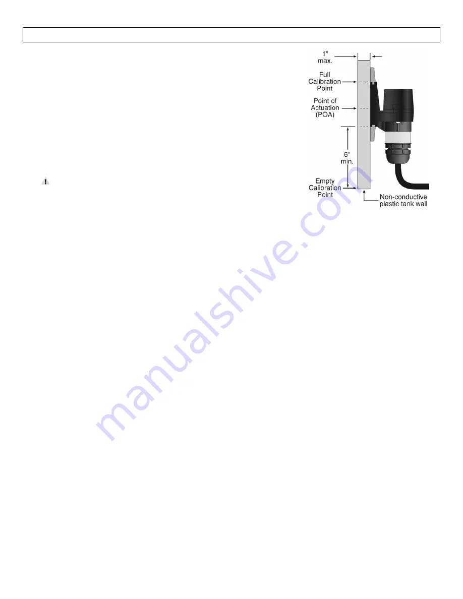
Actuation:
Raise
the
fluid
level
to
the
point
where
the
sensor
sends
a
“wet”
signal
(Input
LED
will
turn
Amber
on
OMEGA
ENGINEERING
controllers).
The
“dry”
signal
should
be
sent
when
the
fluid
level
is
lowered
(Input
LED
will
turn
Green
on
OMEGA
ENGINEERING
controllers).
The
actual
Point
of
Actuation
(POA)
depends
on
many
variables,
including
the
thickness
of
the
wall
and
the
dielectric
value
of
the
liquid.
For
example,
thicker
tank
walls
can
raise
the
POA
while
thinner
walls
could
lower
the
POA.
If
the
POA
needs
to
be
changed,
measure
the
distance
and
remount
the
sensor
in
a
new
location.
Do
not
attempt
to
change
the
Point
of
Actuation
by
intentional
miscalibration.
If
the
sensor
does
not
signal
wet
and
dry
reliably,
it
may
be
that:
the
dielectric
constant
of
the
application
fluid
is
too
low
the
tank
wall
is
too
thick
for
the
application
fluid
there
are
static
or
other
electrical
charges
in
the
fluid
metal
objects
are
within
6"
of
the
sensor
calibration
was
performed
incorrectly
Try
the
calibration
procedure
again,
after
making
corrections
if
possible.
If
the
full
and
empty
states
are
too
similar
dielectrically,
it
may
not
be
possible
to
use
a
capacitance
sensor.
Testing
the
Sensor:
1.
Power:
Apply
power
to
sensor,
by
connecting
power
to
the
controller
and/or
power
supply.
2.
Full
condition:
Fill
the
tank
with
the
application
liquid,
by
filling
the
tank
up
to
the
sensor’s
point
of
actuation.
3.
Test:
With
the
sensor
being
fluctuated
between
wet
and
dry
states,
use
a
multimeter
to
ensure
that
the
correct
signals
are
being
produced
by
the
LVP
‐
51
‐
R
level
switch,
or
observe
the
sensor
indicator
light
in
the
controller.
4.
Point
of
Actuation:
Observe
the
point
at
which
the
rising
or
falling
fluid
level
causes
the
sensor
to
change
state,
and
move
the
installation
of
the
sensor
if
necessary.
Maintenance:
The
LVP
‐
51
‐
R
level
switch
itself
requires
no
periodic
maintenance
except
cleaning
as
required.
However,
periodically
clean
any
coating
or
scaling
on
the
tank
wall
the
sensor
is
attached
to
and
check
the
calibration.
It
is
the
responsibility
of
the
user
to
determine
the
appropriate
maintenance
schedule,
based
on
the
specific
characteristics
of
the
application
liquids.
In
addition,
any
dripping
or
condensation
between
the
sensor
and
the
tank
wall
fitting
may
need
to
be
periodically
cleaned
to
maintain
accuracy.


