


Page 11
omega
.com
CONNECTIONS
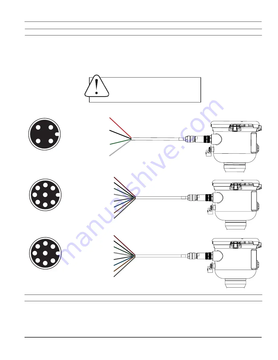
General Cable Information
The meter has two power/output cables that can be installed. The 4-pin cable contains the wires for DC power and
pulse output. The 8-pin cable contains the wires for DC power and pulse, 4-20 mA or Modbus
®
output options
when ordered. See diagrams below for details.
A
vailable in either Battery or external DC versions.
WARNING: BACKUP BATTERIES ARE NOT
INTENDED AS A PRIMARY POWER SOURCE
OF A MAINS (DC or AC) CONFIGURED
METER.
Option IDs
O ID
POWER SOURCE / OUTPUT(S)
BXX
= BATTERY POWER / PULSE SCALED
BXS
= BATTERY POWER / PULSE SCALED / MODBUS
®
D1X/D2X =
DC POWER / PULSE SCALED
D1L/D2L
= DC POWER / PULSE SCALED AND 4-20mA
D1S/D2S
= DC POWER / PULSE SCALED AND MODBUS
®
Red (P1) DC+
Black (P2) DC-
Green (P3) Pulse +
White (P4) Pulse -
Gray (P5) Iso-GND
Blue (P6) B(-)
Orange (P7) A(+)
Brown (P8) N/A
4-20mA Output
Red (P1) DC+
Black (P2) DC-
Green (P3) Pulse +
White (P4) Pulse -
Gray (P5) N/A
Blue (P6) 4-20mA-
Orange (P7) 4-20mA+
Brown (P8) N/A
Modbus
®
Output
Red (P1) DC+
Black (P2) DC-
Green (P3) Pulse +
White (P4) Pulse -
DC/Battery Power with Pulse Output
1
1
1
2
3
4
5
6
7
8
1
2
3
4
1
2
3
4
5
6
7
8
Cable Plug Connector
Arrangement
Cable Plug Connector
Arrangement
Cable Plug Connector
Arrangement
FMG470 Series


