background image

Omega Model CYD211 User’s Manual 


Remote Operation 

4-7 

Visual Basic Serial Interface Program Setup (Continued) 

12.  Add code (provided in Table 4-3). 

a.  In the Code Editor window, under the Object dropdown list, 

select (General). Add the statement: Public gSend as Boolean 

b.  Double Click on cmdSend. Add code segment under Private Sub 

cmdSend_Click( ) as shown in Table 4-3. 

c.  In the Code Editor window, under the Object dropdown list, 

select Form. Make sure the Procedure dropdown list is set at 
Load. The Code window should have written the segment of 
code: Private Sub Form_Load( ). Add the code to this subroutine 
as shown in Table 4-3. 

d.  Double Click on the Timer control. Add code segment under 

Private Sub Timer1_Timer() as shown in Table 4-3. 

e.  Make adjustments to code if different Com port settings are 

being used. 

13.  Save the program. 
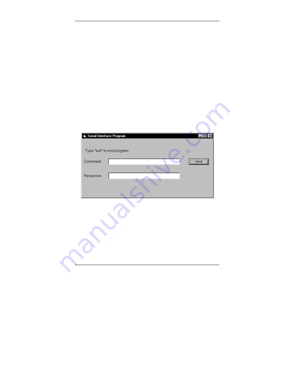
14.  Run the program. The program should resemble the following. 


15.  Type in a command or query in the Command box as described in 

Paragraph 4.1.6.3. 

16.  Press Enter or select the Send button with the mouse to send command. 
17.  Type Exit and press Enter to quit. 
 

Содержание CYD211

Страница 1: ...www omega com e mail info omega com User sGuide CYD211 Single Input Temperature Monitor MADE IN Shop online at ...

Страница 2: ... Guyancourt France Tel 33 0 1 61 37 2900 FAX 33 0 1 30 57 5427 Toll Free in France 0800 466 342 e mail sales omega fr Germany Austria Daimlerstrasse 26 D 75392 Deckenpfronn Germany Tel 49 0 7056 9398 0 FAX 49 0 7056 9398 29 Toll Free in Germany 0800 639 7678 e mail info omega de United Kingdom One Omega Drive River Bend Technology Centre ISO 9002 Certified Northbank Irlam Manchester M44 5BD United...

Страница 3: ...r Lead Cable 2 4 2 5 3 Shielding Sensor Leads 2 5 2 5 4 Instrument Grounding 2 5 2 5 5 Sensor Polarity 2 6 2 5 6 Four Lead Sensor Measurement 2 6 2 5 7 Two Lead Sensor Measurement 2 7 2 5 8 Lowering Measurement Noise 2 7 2 6 ANALOG OUTPUT 2 8 2 7 RELAYS 2 8 2 8 PANEL MOUNTING 2 9 3 OPERATION 3 1 3 0 GENERAL 3 1 3 1 TURNING POWER ON 3 1 3 2 DISPLAY DEFINITION 3 1 3 3 LED ANNUNCIATORS DISPLAY MESSAG...

Страница 4: ...1 Physical Connection 4 1 4 1 2 Hardware Support 4 2 4 1 3 Character Format 4 3 4 1 4 Message Strings 4 3 4 1 5 Message Flow Control 4 4 4 1 6 Serial Interface Basic Programs 4 5 4 1 7 Trouble Shooting 4 12 4 2 SERIAL INTERFACE COMMAND SUMMARY 4 12 4 2 1 Interface Commands 4 15 5 SERVICE 5 1 5 0 GENERAL 5 1 5 1 ERROR MESSAGES 5 2 5 2 1 Instrument Hardware Errors 5 2 5 2 2 Limit Errors 5 3 5 3 OPEN...

Страница 5: ...ensors 1 2 1 2 Sensor Input Performance Chart 1 6 3 1 Sensor Input Types 3 4 3 2 Standard Curves 3 5 3 3 Analog Output Range Scales 3 9 3 4 Analog Output Scales in Sensor Units 3 9 3 5 Conversion Parameters for Temperature in K 3 9 3 6 Model CYD211 Default Values 3 10 3 7 Recommended Curve Parameters 3 12 4 1 Serial Interface Specifications 4 3 4 2 Serial Interface Program Control Properties 4 6 4...

Страница 6: ......

Страница 7: ...rature monitor in an easy to use easily integrated compact instrument With appropriate sensors the Model CYD211 measures temperature from 1 4 to 800 K and in difficult sensing conditions including high vacuum and magnetic fields Alarms relays user configurable analog voltage or current output and a serial interface are standard features on the Model CYD211 Backed by the Omega tradition of excellen...

Страница 8: ...nterface features the Model CYD211 is valuable as a stand alone monitor and is easily integrated into other systems Setup and every instrument function can be performed via serial interface or the front panel of the Model CYD211 High and low alarms can be used in latching mode for error limit detection and in non latching mode in conjunction with relays to perform simple on off control functions T...

Страница 9: ...er curve in non volatile memory Settings Sensor Type Sensor Curve Input Connector DB 25 Front Panel Display Type 5 digit LED Display Units K C F V Ω Display Update Rate Twice per second Temperature Display Resolution 0 001 between 0 99 999 0 01 between 100 999 99 0 1 above 1000 Sensor Units Display Resolution Sensor dependent to 5 digits Display Annunciators K C F V Ω Keys Select Enter s Up Arrow ...

Страница 10: ...00 Ω short circuit protected NA Compliance Voltage NA 10 V Load Regulation NA 0 02 RDG 0 to 500 Ω Scales Temperature Sensor Units Fixed by type 0 20 K 0 100 K 0 200 K 0 325 K 0 475 K 0 1000 K Diodes 1 V 1V 100 Ω Platinum 1 V 100 Ω 1000 Ω Platinum 1 V 1000 Ω NTC Resistor 1 V 1000 Ω Settings Voltage or current scale Connector DB 25 shares input connector General Ambient Temperature 15 35 C 59 95 F a...

Страница 11: ...ctor MAN 211 User s manual NOTE Panel mount hardware installed at factory Calibration Options 8000 CalCurve Compact Disk CD Consists of a calibrated sensor breakpoint table on a CD in ASCII format for customer download 8001 211 CalCurve factory installed Consists of a calibrated sensor breakpoint table factory installed into non volatile memory CAL 211 Instrument calibration with certificate CAL 2...

Страница 12: ... 77 K 2 75 mV K at 300 K 2 75 mV K at 475 K Measurement Resolution Sensor Units Temperature Equivalence 20 µV 0 6 mK at 4 2 K 11 6 mK at 77 K 8 7 mK at 300 K 9 4 mK at 500 K 20 µV 1 mK at 10 K 16 mK at 77 K 10 mK at 300 K 10 mK at 475 K Electronic Accuracy Sensor Units Temperature Equivalence 160 µV 0 01 RDG 10 mK at 4 2 K 152 mK at 77 K 94 mK at 300 K 80 mK at 500 K 160 µV 0 02 RDG 6 mK at 10 K 3...

Страница 13: ...0 mΩ 10 6 mK at 30 K 10 mK at 77 K 10 mK at 300 K 10 mK at 800 K 50 mΩ 1 mK at 4 2 K 33 3 mK at 77 K 500 mK at 300 K 0 004 Ω 0 02 RDG 25 mK at 30 K 18 mK at 77 K 70 mK at 300 K 162 mK at 675 K 187 mK at 800 K 0 06 Ω 0 04 RDG 40 mK at 30 K 33 mK at 77 K 135 mK at 300 K 370 mK at 800 K 0 1 Ω 0 04 RDG 1 mK at 4 2 K 88 mK at 77 K 1 144 K at 300K 0 2 mΩ 5 PPM of reading per C 2 0 mΩ 5 PPM of reading pe...

Страница 14: ...echnology Equipment IEC 60950 Ground The Instrument To minimize shock hazard the optional instrument power supply is equipped with a 3 conductor AC power cable Plug the power cable into an approved three contact electrical outlet or use a three contact adapter with the grounding wire green firmly connected to an electrical ground safety ground at the power outlet The power jack and mating plug of ...

Страница 15: ...install substitute parts or perform any unauthorized modification to the instrument Return the instrument to an authorized Omega representative for service and repair to ensure that safety features are maintained Cleaning Do not submerge instrument Clean only with a damp cloth and mild detergent Exterior only 1 4 SAFETY SYMBOLS ...

Страница 16: ...Omega Model CYD211 User s Manual 1 10 Introduction This Page Intentionally Left Blank ...

Страница 17: ...ainer and shipping materials until all contents have been accounted for Check off each item on the packing list as it is unpacked Instruments may be shipped as several parts The items included with the Model CYD211 are listed as follows Items Included with Model CYD211 Temperature Monitor Model CYD211 Instrument Model CYD211 User s Manual Input Output Mating Connector and Shell Panel Mount Hardwar...

Страница 18: ...Rear bmp Description Details 1 POWER 5 pin DIN Paragraph 2 3 Figure 5 2 2 SERIAL I O DTE DE 9 Paragraph 4 1 1 Figure 5 4 3 INPUT OUTPUT DB 25 Paragraphs 2 4 2 6 Figure 5 3 Figure 2 1 Model CYD211 Rear Panel 2 3 POWER INPUT CONNECTOR Power is supplied to the Model CYD211 through a 5 pin DIN connector located on the rear panel of the instrument There is no power switch on the instrument so it is off...

Страница 19: ... 1 A 15 V at 400 mA and 15V at 400 mA One power supply can provide power for up to three Model CYD211 s with a user supplied adapter cable The power supply is CE Certified and meets or exceeds the following safety standards UL 1950 CSA C22 2 and IEC 60950 2 5 SENSOR INPUT This paragraph details how to connect diode and resistor sensors to the Model CYD211 input Refer to Paragraph 3 5 to configure ...

Страница 20: ...e Between the instrument and vacuum shroud heat leak is not a problem but errors from noise pick up need to be minimized Larger conductor 22 to 28 AWG stranded copper wire is recommended because it has low resistance yet remains flexible when several wires are bundled in a cable The arrangement of wires in a cable is also important For best results twist voltage leads V and V together and twist cu...

Страница 21: ...del CYD211 does not provide isolation between measurement circuits and chassis ground The measurement leads have a finite impedance to chassis ground and should not be tied to ground outside the instrument or an error in reading may result The Model CYD211 has the best noise performance when the chassis is tied to earth ground This connection should be made at only one point so as to avoid ground ...

Страница 22: ... not the most accurate DT 670 SD Diode Sensor Leads Anode Cathode 2 5 6 Four Lead Sensor Measurement All sensors including both two lead and four lead can be measured with a four lead technique Four lead measurement eliminates the effect of lead resistance on the measurement If it is not taken out lead resistance is a direct error when measuring a sensor I V I V Four Lead Diode Four Lead Platinum ...

Страница 23: ...t 4 2 K the error in temperature would be only 3 mK At 77 K the sensitivity of a silicon diode is lower so the error would be close to 50 mK Again this may not be a problem for every user 2 5 8 Lowering Measurement Noise Good instrument hardware setup technique is one of the least expensive ways to reduce measurement noise The suggestions fall into two categories 1 Do not let noise from the outsid...

Страница 24: ...ut connector See Figure 2 3 The terminal marked analog output signal is the output voltage terminal the terminal marked analog output ground is the ground and is attached to chassis ground inside the instrument It is not recommended to attach the analog output ground to a ground outside the instrument The output should be read by an instrument with an isolated or differential input wherever possib...

Страница 25: ...n place Remove the 2 panel mount brackets by sliding them towards the rear of the unit Then place the unit into the panel cutout Slide the two panel mount brackets back into the case of the instrument Reinstall the 2 set screws and tighten them until the instrument is secure The Model CYD211 can also be purchased with either of two panel mount adapters The Model CYD2111 or 2112 will mount 1 or 2 T...

Страница 26: ...Omega Model CYD211 User s Manual 2 10 Installation Cutout_Panels bmp Figure 2 5 2111 and 2112 Panel Mount Adapters ...

Страница 27: ...ading cycle and temperature or sensor units readings should appear on the display Messages will appear in the reading location on the display if the measurement input has not been fully configured Messages listed in Paragraph 5 3 1 Instrument Hardware Errors are related to the instrument hardware and may require help from Omega service The messages listed in Paragraph 5 3 2 Limit Errors do not ind...

Страница 28: ...Kelvin F The display units are in degrees Fahrenheit V Ω The display units are in sensor units either volts or ohms depending on input type Alarm messages are displayed alternately with the reading when an alarm condition exists If both a high and low alarm condition exists can only happen when latching alarms are active then the display will alternate between the current reading and the alarm hig...

Страница 29: ...nlock the keypad 3 4 2 General Keypad Operation The CYD211 has two keypad operations setting selection and data entry Setting Selection Allows the user to select from a finite list of parameter values During setting selection the s and t keys are used to select a parameter value Enter is used to accept the change and advance to the next parameter Select will cancel the change to that parameter and...

Страница 30: ...appears press the Enter key Proceed to Paragraph 3 5 2 to select a temperature curve or press the Select key to return to the normal display Table 3 1 Sensor Input Types Display Message Input Type Excit ation Sensor Type Curve Format Coef ficient Omega Sensors 2 5 V 10 µA Silicon Diode V K Neg DT 470 DT 670 gaAlas 7 5 V 10 µA Gallium Aluminum Arsenide Diode V K Neg TG 120 Series 250 Pt 250 Ω 1 mA ...

Страница 31: ...e recommended format for the input type selected Refer to Table 3 1 NOTE The sensor reading can always be displayed in sensor units If a temperature response curve is selected for an input its readings may also be displayed in temperature To select a curve continue from the input type selection Paragraph 3 5 1 or press the Select key use the s or t key to select input then press the Enter key twic...

Страница 32: ...ponse curve is chosen the alarm function will not operate Refer to Paragraph 3 5 2 for curve selection If an alarm activates for the input the display flashes between the current reading and or for high and low alarms respectively The two relays can also be tied to alarm functions refer to Paragraph 3 7 Latching Alarms Often used to detect faults in a system or experiment that require operator int...

Страница 33: ...play will return to normal operation 3 7 RELAY SETUP There are two relays on the CYD211 numbered 1 and 2 They are most commonly thought of as alarm relays but they may be manually controlled The relays are rated for 30 VDC and 1 A The terminals are in the Input Output connector on the CYD211 rear panel See Figure 2 3 When using relays with alarm operation set up the alarms first Paragraph 3 6 Rela...

Страница 34: ...of full scale The output is limited by a 10 V compliance voltage so the largest resistive load that the output can drive in current mode is 500 Ω The analog output has two modes voltage and current and six ranges The ranges are listed in Table 3 3 The low output is the temperature that produces zero output 0 V or 4 mA and the high output is the temperature that produces full output 10 V or 20 mA I...

Страница 35: ... directly proportional to the temperature reading For the 4 20 mA output the following formula converts output current to temperature T A B IOUT where T temperature in Kelvin IOUT output current in mA and A and B are constants from Table 3 5 For the 0 10 V output the following formula converts output voltage to temperature T C VOUT where T temperature in Kelvin VOUT output voltage and C is a const...

Страница 36: ...d EEPROM The default values of the Model CYD211 are shown below in Table 3 6 Resetting to default values does not affect the user curve or the calibration data To reset the Model CYD211 to default values press and hold both the s or t keys for 10 seconds All of the LED digits will illuminate when the memory has been reset Release the buttons and the display will return to normal operation Table 3 ...

Страница 37: ...name can be entered Serial Number Up to a 10 character sensor serial number consisting of both numbers and letters Format The format parameter tells the instrument what breakpoint data format to expect Different sensor types require different formats Formats for Omega sensors are V K Volts vs Kelvin for Diode sensors Ω K Resistance vs Kelvin for platinum RTD sensors Log Ω K Log Resistance vs Kelvi...

Страница 38: ... resolution is also 6 digits in sensor units The curve format parameter defines the range and resolution in sensor units as shown in Table 3 7 The sensor type determines the practical setting resolution Table 3 7 lists recommended sensor units resolutions For most sensors additional resolution is ignored The breakpoints should be entered with the sensor units value increasing as point number incre...

Страница 39: ...However any two devices claiming RS 232C compatibility cannot necessarily be plugged together without interface setup The remainder of this paragraph briefly describes the key features of a serial interface that are supported by the instrument A customer supplied computer with similarly configured interface port is required to enable communication 4 1 1 Physical Connection The Model CYD211 has a 9...

Страница 40: ...nd common computers The instrument uses drivers to generate the transmission voltage levels required by the RS 232C standard These voltages are considered safe under normal operating conditions because of their relatively low voltage and current limits The drivers are designed to work with cables up to 50 feet in length 4 1 2 Hardware Support The Model CYD211 interface hardware supports the follow...

Страница 41: ... and line feed LF 0AH are used to indicate the end of a message string Table 4 1 Serial Interface Specifications Connector Type 9 pin D style plug Connector Wiring DTE Voltage Levels EIA RS 232C Specified Transmission Distance 50 feet maximum Timing Format Asynchronous Transmission Mode Half Duplex Baud Rate 9600 Handshake Software timing Character Bits 1 Start 7 Data 1 Parity 1 Stop Parity Odd Te...

Страница 42: ...a parameter Response data formats are listed along with the associated queries in Paragraph 4 2 1 The response is sent as soon as possible after the instrument receives the query Typically it takes 10 ms for the instrument to begin the response Some responses take longer 4 1 5 Message Flow Control It is important to remember that the user program is in charge of the serial communication at all tim...

Страница 43: ...d implement these programs not included with the instrument the concepts illustrated apply to almost any application where these tools are available 4 1 6 1 Visual Basic Serial Interface Program Setup The serial interface program Table 4 3 works with Visual Basic 6 0 VB6 on an IBM PC or compatible with a Pentium class processor A Pentium 90 or higher is recommended running Windows 95 or better wit...

Страница 44: ...fined in Table 4 2 11 Save the program Table 4 2 Serial Interface Program Control Properties Current Name Property New Value Label1 Name Caption lblExitProgram Type exit to end program Label2 Name Caption lblCommand Command Label3 Name Caption lblResponse Response Text1 Name Text txtCommand blank Text2 Name Text txtResponse blank Command1 Name Caption Default cmdSend Send True Form1 Name Caption f...

Страница 45: ... sure the Procedure dropdown list is set at Load The Code window should have written the segment of code Private Sub Form_Load Add the code to this subroutine as shown in Table 4 3 d Double Click on the Timer control Add code segment under Private Sub Timer1_Timer as shown in Table 4 3 e Make adjustments to code if different Com port settings are being used 13 Save the program 14 Run the program T...

Страница 46: ...s are CR LF ZeroCount 0 Initialize counter strReturn Clear return string strHold Clear holding string If frmSerial MSComm1 PortOpen True Then Close serial port to change settings frmSerial MSComm1 PortOpen False End If frmSerial MSComm1 CommPort 1 Example of Comm 1 frmSerial MSComm1 Settings 9600 o 7 1 Baud Parity Data Stop frmSerial MSComm1 InputLen 1 Read one character at a time frmSerial MSComm...

Страница 47: ...ZeroCount ZeroCount 1 Timeout at 2 seconds Else ZeroCount 0 Reset timeout for each character strHold frmSerial MSComm1 Input Read in one character strReturn strReturn strHold Add next character to string End If Wend Get characters until terminators If strReturn Then Check if string empty strReturn Mid strReturn 1 InStr strReturn Term 1 Strip terminators Else strReturn No Response Send No Response ...

Страница 48: ... is running try the following commands and observe the response of the instrument Input from the user is shown in bold and terminators are added by the program The word term indicates the required terminators included with the response ENTER COMMAND IDN Identification query Instrument will return a string identifying itself RESPONSE LSCI MODEL211 2110000 032502 term ENTER COMMAND KRDG Kelvin readi...

Страница 49: ...EXIT THEN CLOSE 1 END Get out on Exit CMD CMD TERM PRINT 1 CMD Send command to instrument IF INSTR CMD 0 THEN Test for query RS If query read response N 0 Clr return string and count WHILE N TIMEOUT AND INSTR RS TERM 0 Wait for response IN INPUT LOC 1 1 Get one character at a time IF IN THEN N N 1 ELSE N 0 Add 1 to timeout if no chr RS RS IN Add next chr to string WEND Get chrs until terminators I...

Страница 50: ...ll modem adapter if not 2 Always send terminators 3 Send entire message string at one time including terminators Many terminal emulation programs do not 4 Send only one simple command at a time until communication is established 5 Be sure to spell commands correctly and use proper syntax Old Installation No Longer Working 1 Power instrument off then on again to see if it is a soft failure 2 Power ...

Страница 51: ...y name Brief description of query Form of the query input BRIGT Input Display Brightness Query BRIGT input term Definition of returned parameter Syntax of returned parameter Returned bright term nn refer to command for description Format Query eps Key Q Begins common interface command Required to identify queries aa String of alpha numeric characters nn String of number characters that may include...

Страница 52: ...L Curve Delete Command 17 CRVHDR Curve Header Command 17 CRVHDR Curve Header Query 18 CRVPT Curve Data Point Command 18 CRVPT Curve Data Point Query 18 DFLT Factory Defaults Command 19 DISPFLD Displayed Field Command 19 DISPFLD Displayed Field Query 19 FRDG Fahrenheit Reading Query 19 INCRV Input Curve Number Command 19 INCRV Input Curve Number Query 20 INTYPE Input Type Parameter Command 20 INTYP...

Страница 53: ... enable term Format n nnn n nnn n nn n n off on Determines whether the instrument checks the alarm for input where 0 off and 1 on high value Sets the value the temperature is checked against to activate the high alarm low value Sets the value the temperature is checked against to activate low alarm deadband Sets the value that the temperature must change outside of an alarm condition to deactivate...

Страница 54: ...term Format n n mode Specifies mode in which analog output operates where 0 voltage mode and 1 current mode range Sets temperature range that analog output uses as full scale 0 0 20 K 3 0 325 K 1 0 100 K 4 0 475 K 2 0 200 K 5 0 1000 K Example ANALOG 0 1 term Sets analog output to voltage mode 0 10V 100 0 K at 100 output 10 0 V and 0 0 K at 0 output 0 0 V ANALOG Analog Output Parameter Query Input ...

Страница 55: ...ecifies user curve to delete Only valid entry is 21 Curve number is used to retain compatibility with existing instrument line Curve number 21 must be sent with the command or else the command will be ignored CRVHDR Curve Header Command Input CRVHDR curve name SN format limit value coefficient term Format nn aaaaaaaaaaaaaaa aaaaaaaaaa n nnn nnn n curve Specifies user curve Valid entry 21 name Curv...

Страница 56: ...n nnnnnnn nnnnnnn curve Specifies which curve to configure Valid entry 21 index Specifies curve points index Valid entries 1 200 units value Specifies sensor units for point to 6 digits temp value Specifies the corresponding temperature in Kelvin for this point to 6 digits Remarks Configures a user curve data point To finalize curve entry send the RST command or cycle the instrument power after al...

Страница 57: ...elvin reading for the input DISPFLD Displayed Field Query Input DISPFLD term Returned source term Format n Refer to command for description FRDG Fahrenheit Reading Query Input FRDG term Returned temp value term Format nnnnnn Remarks Also see the RDGST command INCRV Input Curve Number Command Input INCRV curve number term Format nn curve number Specifies which curve the input uses If specified curv...

Страница 58: ...de 4 1000 Ω Platinum 2 100 Ω Platinum 250 5 NTC RTD Example INTYPE 0 term Sets input sensor type to silicon diode INTYPE Input Type Parameter Query Input INTYPE term Returned sensor type term Format n Refer to command for description KEYST Keypad Status Query Input KEYST term Returned keypad status term Format n 1 key pressed 0 no key pressed Remarks Returns keypad status since the last KEYST KEYS...

Страница 59: ...weighting term Format nnn Remarks Integer returned represents sum of bit weighting of the input status flag bits 000 indicates a valid reading is present Bit Bit Weighting Status Indicator 1 2 A D not responding 2 4 Alarm low 3 8 Alarm high 4 16 Temperature under range 5 32 Temperature over range 6 64 Sensor units zero 7 128 Sensor units over range RELAY Relay Control Parameter Command Input RELAY...

Страница 60: ...ut RELAY relay number term Format n relay number Specifies which relay to query 1 low alarm relay 2 high alarm relay Returned n Refer to command for description SRDG Sensor Units Input Reading Query Input SRDG term Returned sensor units value term Format nnnnnn Remarks Also see the RDGST command ...

Страница 61: ...erly the instrument may require repair 5 1 1 Instrument Hardware Errors ErR 01 Indicates that there is a hardware problem in the instrument memory This error is not correctable by the user and the factory should be consulted ErR 02 Indicates there is a soft error in the instrument memory This error can be corrected reinitializing memory Reinitializing memory sets the instrument to defaults and era...

Страница 62: ...ly qualified personnel should perform this procedure REMOVAL 1 Disconnect the power cord from rear of unit 2 If attached remove from panel mount 3 Use a Phillips screwdriver to remove the four flat head screws from the corners of the rear panel 4 Slide out the PC board assembly The rear panel is attached to the PC board INSTALLATION 1 Slide the PC board assembly in from the rear of the chassis mak...

Страница 63: ...closure REMOVAL procedure in Paragraph 5 4 2 Locate the IC on the main circuit board See Figure 5 1 Note orientation of existing IC CAUTION The IC is an Electrostatic Discharge Sensitive ESDS device Wear shock proof wrist straps resistor limited to 5 mA to prevent injury to service personnel and to avoid inducing an Electrostatic Discharge ESD into the device 3 Use IC puller to remove existing IC ...

Страница 64: ...Omega Model CYD211 User s Manual 5 4 Service 211_PCB bmp Figure 5 1 Model CYD211 Main PCB Layout ...

Страница 65: ...P 211 2 3 bmp Pin Description Pin Description 1 No Connection 2 Shield 14 Shield 3 I 15 I 4 V 16 V 5 Shield 17 Shield 6 Analog Output Signal 18 Analog Output Ground 7 No Connection 19 No Connection 8 Low Alarm COM 20 Low Alarm N O 9 Low Alarm N C 21 No Connection 10 No Connection 22 No Connection 11 High Alarm COM 23 High Alarm N O 12 High Alarm N C 24 No Connection 13 No Connection 25 No Connecti...

Страница 66: ...1 No Connection 2 TD out 1 DCD in 2 Receive Data RD in 3 RD in 2 RD in 3 Transmit Data TD out 4 RTS out 3 TD out 4 Data Terminal Ready DTR out 5 CTS in 4 DTR out 5 Ground GND 6 DSR in 5 GND 6 No Connection 7 GND 6 DSR in 7 Data Terminal Ready DTR out tied to 4 8 DCD in 7 RTS out 8 No Connection 20 DTR out 8 CTS in 9 No Connection 22 Ring in in 9 Ring in in Figure 5 4 RS 232 DTE Connector ...

Страница 67: ... Serial Interface Cable Wiring The following are suggested cable wiring diagrams for connecting the CYD211 Serial Interface to various Customer Personal Computers PCs NOTE Same as null modem cable design except PC CTS is provided from the CYD211 on DTR ...

Страница 68: ...Omega Model CYD211 User s Manual 5 8 Service This Page Intentionally Left Blank ...

Страница 69: ...s follows Model Description of Accessory 106 253 Sensor input mating connector DB 25 106 264 Shell for sensor input mating connector 2111 Panel mount adapter for one CYD211 into 105 mm Wide 132 mm High 4 1 5 2 inches mounting plate See Fig 2 4 2112 Panel mount adapter for two CYD211s into 105 mm Wide 132 mm High 4 1 5 2 inches mounting plate See Fig 2 4 8000 CalCurve floppy disk Consists of a cali...

Страница 70: ... Sensor No Sensor Description Series DT 420 The smallest silicon diode Temperature Sensor available For installation on flat surfaces Sensor incorporates the same type of silicon chip used in the Series DT 470 and DT 471 Series DT 450 Silicon Diode Miniature Temperature Sensor Same silicon chip used in the DT 470 configured for installation in recesses as small as 1 6 mm diameter by 3 2 mm deep Se...

Страница 71: ...005 0 44647 0 45860 0 50691 0 51892 0 55494 0 60275 0 63842 0 67389 0 70909 0 74400 0 77857 0 80139 30 31 32 33 34 35 36 37 38 39 40 41 42 43 44 45 46 47 48 49 50 51 52 53 54 55 56 57 58 170 0 160 0 150 0 145 0 140 0 135 0 130 0 125 0 120 0 115 0 110 0 105 0 100 0 095 0 090 0 085 0 080 0 075 0 070 0 065 0 058 0 052 0 046 0 040 0 039 0 036 0 034 0 033 0 032 0 0 82405 0 84651 0 86874 0 87976 0 89072...

Страница 72: ... 27 28 29 30 31 32 33 34 35 36 37 38 39 40 41 42 43 44 45 46 47 48 49 50 87 0 81 0 75 0 69 0 63 0 56 4 49 0 38 7 35 7 33 3 31 2 29 6 28 3 27 3 26 5 25 8 25 2 24 7 24 3 24 0 23 7 23 3 22 8 22 0 21 3 1 01064 1 02125 1 03167 1 04189 1 05192 1 06277 1 07472 1 09110 1 09602 1 10014 1 10393 1 10702 1 10974 1 11204 1 11414 1 11628 1 11853 1 12090 1 12340 1 12589 1 12913 1 13494 1 14495 1 16297 1 17651 51...

Страница 73: ...5 26 27 28 29 320 0 305 0 295 0 285 0 280 0 270 0 250 0 195 0 165 0 140 0 130 0 125 0 115 0 110 0 100 0 95 0 90 0 85 0 77 4 65 0 60 0 36 0 20 0 19 0 18 0 14 0 12 0 11 0 10 0 0 2968 0 3382 0 3640 0 3911 0 4050 0 4341 0 4896 0 6408 0 7255 0 7971 0 8245 0 8376 0 8625 0 8769 0 9049 0 9184 0 9314 0 9440 0 9626 0 9958 1 0100 1 0747 1 1162 1 1290 1 1500 1 3161 1 3656 1 3850 1 4000 ...

Страница 74: ...0 0 800 0 3 820 4 235 5 146 5 650 6 170 6 726 7 909 9 924 12 180 15 015 19 223 23 525 32 081 46 648 62 980 75 044 98 784 116 270 131 616 148 652 165 466 182 035 198 386 216 256 232 106 247 712 261 391 276 566 289 830 030 0 032 0 036 0 038 0 040 0 042 0 046 0 052 0 058 0 065 0 075 0 085 0 105 0 140 0 180 0 210 0 270 0 315 0 355 0 400 0 445 0 490 0 535 0 585 0 630 0 675 0 715 0 760 0 800 0 38 20 42 ...

Страница 75: ...se shall not exceed the purchase price of the component upon which liability is based In no event shall OMEGA be liable for consequential incidental or special damages CONDITIONS Equipment sold by OMEGA is not intended to be used nor shall it be used 1 as a Basic Component under 10 CFR 21 NRC used in or with any nuclear installation or activity or 2 in medical applications or used on humans Should...

Страница 76: ...ators Turbine Paddlewheel Systems Totalizers Batch Controllers pH CONDUCTIVITY pH Electrodes Testers Accessories Benchtop Laboratory Meters Controllers Calibrators Simulators Pumps Industrial pH Conductivity Equipment DATA ACQUISITION Data Acquisition Engineering Software Communications Based Acquisition Systems Plug in Cards for Apple IBM Compatibles Datalogging Systems Recorders Printers Plotter...

Отзывы: