


33
07
AWG22
AWG18 ORANGE
AWG18 WHITE
YV1 (**)
ST1 (**)
PE
PE
TERMISTORI MOTORE COMPRESSORE
COMPRESSOR MOTOR THERMISTORS
ALLARME REMOTO
(REMOTE ALARM)
L3
L2
L1
LINEA
(ELECTRICAL POWER SUPPLY)
MOTORE ELETTROVENTOLA
RAFFREDDAMENTO
(FU3)
(FU5)
(FU6)
COMANDO ON-OFF REMOTO
(REMOTE ON/OFF)
THERMAL PROTECTION COOLING FAN MOTOR
PROTEZIONE TERMICA
E.VENTOLA RAFFREDDAMENTO
COOLING FAN MOTOR
(FU2)
(FU1)
+
-
L3
L2
L1
2
1
5
4
3
2
1
D1
FU6
control terminal
morsettiera
board
controllo
control terminal
morsettiera
board
controllo
36 (-)
35 (+)
W3
V3
U3
CN9
RS485
CN6
CN7
CN3
CN2
2
1
10
9
8
7
6
5
4
3
2
1
B
A
1 2
1
2
1
2
3
1
CN1
CN4
3
4
5
6
3 4 5 6 7
2 3 4 5 6 7 8 9
12 11 10 9 8 7 6 5 4
FU2
FU3
FU1
FU5
18
22
0 18
32
31
18
0
17
22
22
32 31
ST1
EXTRACTION MOTOR
ELECTRICAL CABINET
(230VA)
VANO ELETTRICO
ESTRAZIONE
MOTORE
KM2
MV2
1
REMOTE ALARM
A DISTANZA
ALL.
CUMULATIVO
19
20
RT
72
71
72
71
20
19
RT
MC
3
72
71
72
71
XI = Lower Terminal Board
XI = Morsettiera inferiore
(230)
(***)
L3
L2
L1
4
09
2
2
2
(***)
W3
U3 V3
BP
T
S
R
19
20
board
control terminal
controllo
morsettiera
24Vac/dc
D2 (OPTIONAL)
RS232 RS485
XS = Morsettiera superiore
XS = Upper Terminal Board
(575)
(0)
XDI(1)
XD24(4)
XAI
XAI
XR03
ELETTROVENTOLA
0
246
245
(0)
(24)
(24)
(0)
PE
KM1
YV1 KM2
KM3
COOLING FAN MOTOR
THERMAL PROTECTION
COOLING FAN MOTOR
COMPRESSOR MOTOR
KM1
32
31
7
6
012
KM2
018
GF
U
FU4
L3
L2
L1
V W
COMPRESSORE
MOTORE
KM1
2
ST3
Q
RAFFREDDAMENTO
09
PROT.TERMICA
MOTORE
RAFFREDDAMENTO
MOTORE
ELETTROVENTOLA
MV3
3
KM3
10
24
5
2
4 4
2
2
2
09
2
2
3
5
2
2
(***)
00
10
SB
KR
11
14
12
L3
L2
L1
11
0
L21
TC1
13
L31
L11
1
(115)
(575)
(0)
TC2
AWG 22 BLACK
AWG1 BLACK
AWG1 BLACK
AWG18 BLACK
AWG18 BLUE
AWG18 RED
AWG18 WHITE
AWG10 BLACK
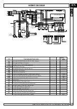
EN
WIRING DIAGRAM
Ref.
Denominazione/Denomination
100Hp
kW 75
TC1
Trasformatore Pr.0/230/575 300VA Sec.0/24 (20VA) 0/24 (230VA) (Transformer)
TC2
Trasformatore Pr.0/575 Sec.0/115 (Transformer)
SB
Pulsante eme n.2 NC 230V 10A (Emergency button)
FU1.FU2.FU3
Fusibili ceramici 2A (Ceramic fuses)
FU4
Base portafusibile tripolare 600V (Tripolar fuse holder base)
160A (NH1gG)
FU5
Fusibili ceramici 10A (Ceramic fuses)
FU6
Fusibile ceramico 1A (Ceramic fuses)
KM1
Contattore linea alimentazione inverter bob.24 V 50/60 Hz (Inverter line contactor)
75kW
KM2
Contatt. estr.vano elettrico (Electrical cabinet extraction contactor) bob.24 V 50/60 Hz
3kW(*)
KM3
Contattore ventola raffreddamento (Cooling fan contactor) bob.24 V 50/60 Hz
5,5kW(*)
GF
Inverter (Inverter)
75 kW
KR
Dispositivo sequenza fasi (Phase sequence device)
YV1
El. compressore 24 V 50/60 Hz (Solenoide valve compressor pump)
BP
Trasduttore di pressione 0-16 Bar 4-20mA (Pressure transducer)
D1
Controllore elettronico (Electronic controller) 24VAC
D2
Dispositivo SMS (SMS Device) 24 VAC (optional)
RT
Termistori motore compressore (Compressor motor thermistors)
ST1
Sonda termica mandata vite (Temperature probe compressor pump)
Sez. cavo motore (motor cable cross-section area)(mmq) SCHERMATO
4XAWG1
NOBEL DV 45-55_NOBEL 75 E DV CSA - Cod.197EE0696ML - Rev.0 02/2020


