8
Installation
ASSEMBLY INSTRUCTIONS
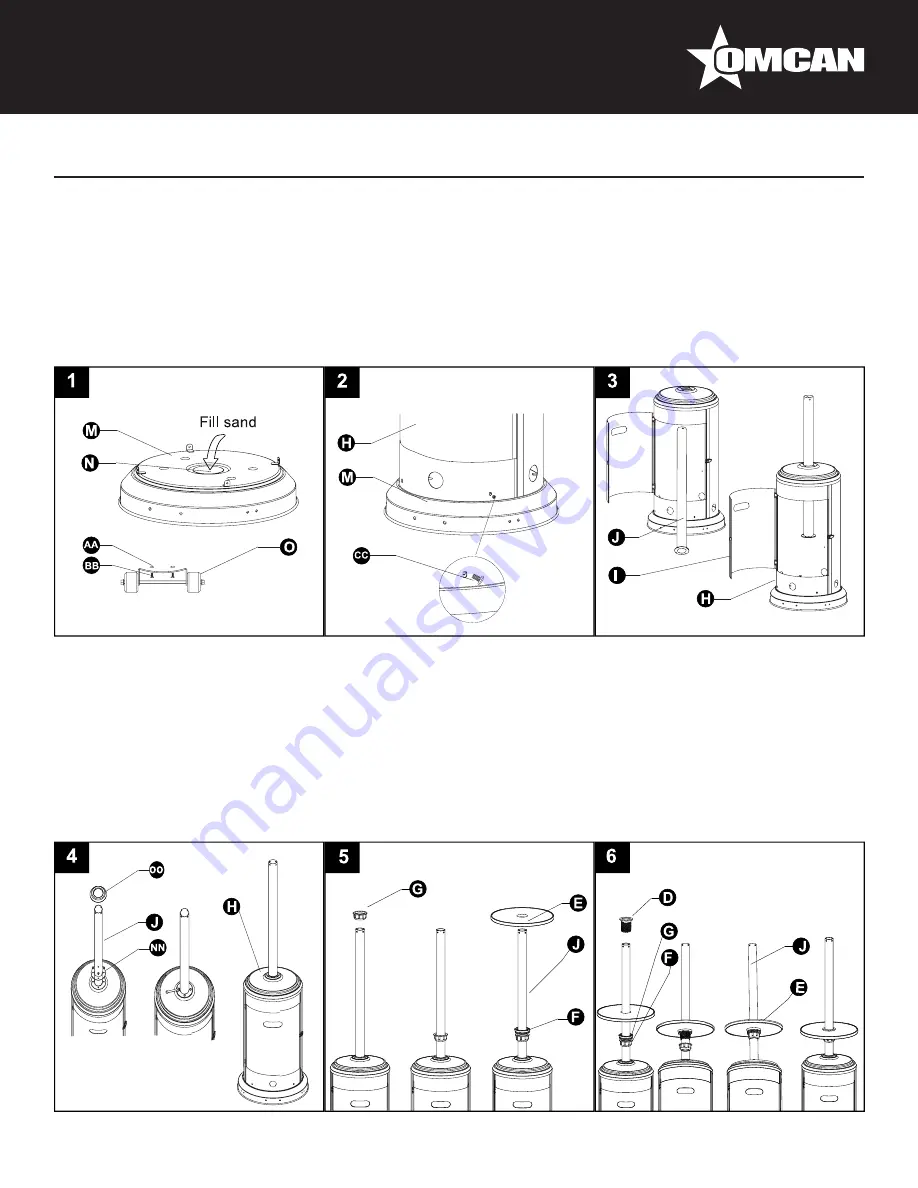
1.
Line up holes on the bracket of wheel assembly (O) with the corresponding holes on base (M), then insert
M8 x 16 mm bolts (BB) through holes. Hand tighten with M8 flange nuts (AA). Be sure the wheel assembly
(O) is parallel to the base (M).
Note: To improve stability, the preassembled bucket (N) can be filled with sand (not included).
2.
Attach cylinder housing (H) loosely to base (M) with M5 x 8 mm screws (CC).
3. Open the preassembled door (I) on cylinder housing (H) and place post (J) through the hole on the top.
4.
Secure post (J) to cylinder housing (H) using the reinforced ring (NN), M6 x 10 mm bolts (DD) and Φ6
small flat washers (EE). Fasten and cover with the deck ring (OO).
5. Slide fastening nut (G) down the post (J) with the rounded side facing down. Next, slide the tightening
spacer (F) down the post (J) with the smaller side facing down. Put the table (E) on the post (J) with the
metallic side facing up.
6. Insert the screw coupler (D) on the post (J), inserting it through the middle of the table (E) on the post
(J). Thread the tightening spacer (F) on the bottom of the table (E) counterclockwise onto the screw
coupler (D). Tighten securely to hold the table (E) to the screw coupler (D). Thread the fastening nut (G)
counterclockwise. Tighten securely to lock in place. Loosen the fastening nut (G) to adjust the position of
the table (E) on the post (J).
Содержание PH-CN-0014
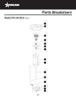
Страница 17: ...17 Parts Breakdown Model PH CN 0014 43595...


