background image


D877 MGB Rev01 HE250.docx    


25/50 

3.3 

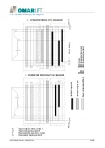
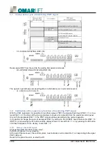
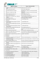
Test device against uncontrolled movement (DSP=uc, up ) 


It describes a procedure to verify the conformity of the device in accordance with section 6.3.13 of the EN81-
20 regulation. 
Before proceeding, verify, however, the manual of the electrical panel, the operations necessary for the tests. 
Usually it predisposes the implant so as to exclude the possibility of calls and open the electric chain safeties 
at the level of the floor doors (for the system doors must be open even if physically closed). So the cab has to 
move up out of the door zone and stop responding for intervention of the safety circuit 
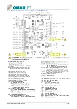
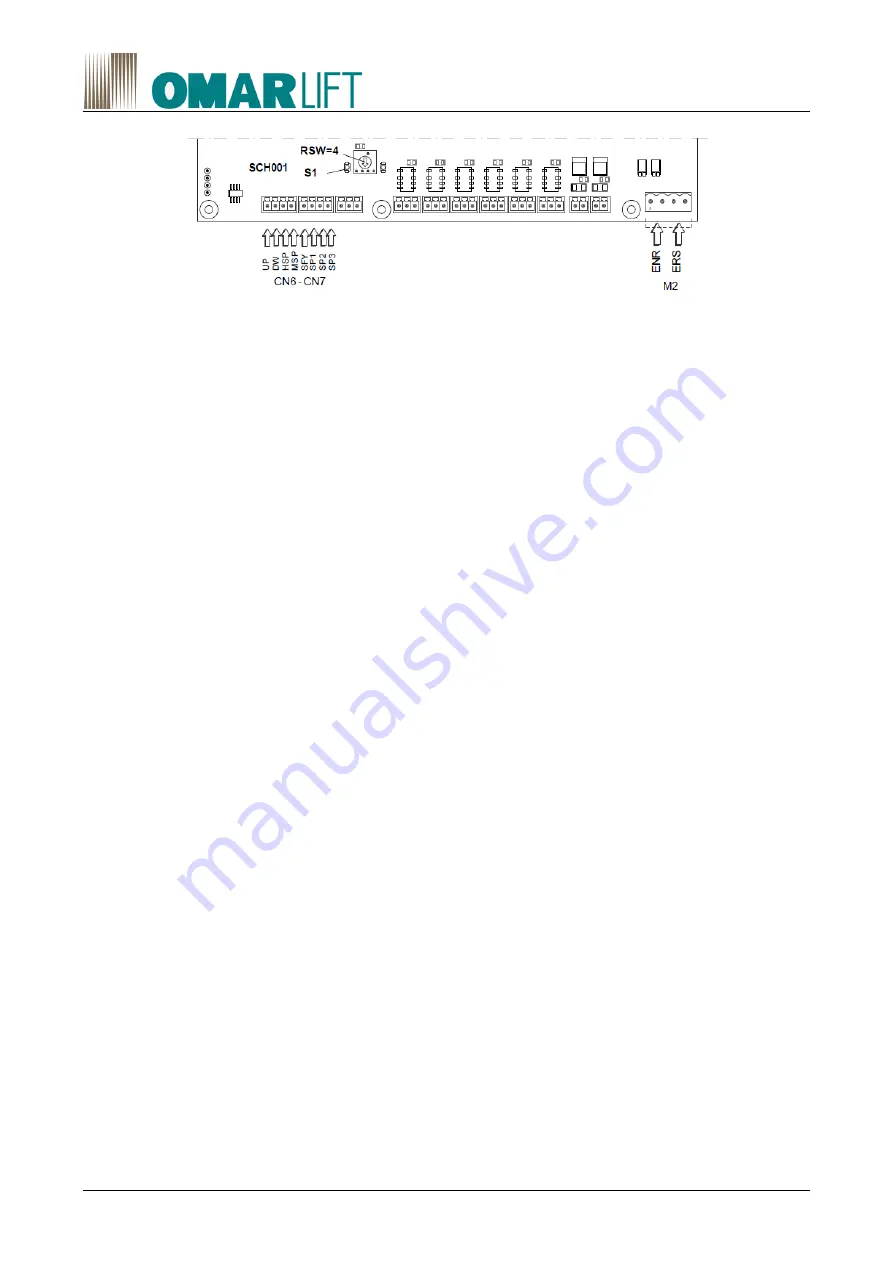
Setting on the electronic board SCH001 the switch RSW = 4 (DSP = UC) and pressing the S1 button until UP 
appears  on  the  display,  it  predisposes  the  valve  group  to perform  the  next  cycle  of  ascent  or  descent  with 
nominal speed, even during the respective releveling maneuvers. 

3.3.1 

Ascent with empty car, and positioned in the upper part of the compartment 

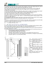
Open,  manually,  the  emergency  lowering  valve,  pulling  down  the  cabin  until  the  intervention  of  re-leveling 
uphill. When the re-leveling intervenes, the system will start uphill at nominal speed and the switch intended 
to detect the movement uncontrolled must act by stopping the cab. Check that the stop position of the cab 
complies with the requirements in section 5.6.7.5 of EN 81-20. 

3.3.2 

Descent with a full load in the cabin, and the cabin located at the bottom of the compartment 

Using the hand pump, moving uphill the plant, until the start of the downhill re-leveling. 
The re-leveling intervenes when, the plant will start descending at nominal speed and the switch purpose of 
identifying the uncontrolled movement must act by stopping the cabin. 
The device must operate the stop element, i.e., interrupt signals to the valve group during the descent, before 
the cab moves away from 200 mm from the floor. 
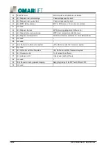
In particular, to activate the stop element, the device must disconnect, on SCH001 card, the inputs of the ENR 
solenoid valves and ERS 
on the M2 terminal board, and in any case are to exclude the input signals to the card, the CN6-7 connectors. 
Check that the stop position of the cab complies with the requirements in section 5.6.7.5 of EN 81-20. 
At  the  end  of  each  maneuver,  performed  during  the  test,  the  card  no  longer  provide  the  RDY  signal,  if  not 
setting a new test, by pressing the S1 button again, or a normal operation changing the switch RSW = 0. 
At the end of the test, restore normal system operation. 
Note: As an alternative to the use of RSW switch, you can activate the test condition by setting the parameter 
P711  to  the  value  1.  At  the  end  of  the  test  the  value  of  the  parameter  returns  automatically  to  0.  For  the 
verification of the monitoring function of the protective equipment refer to steps 3.5 or 3.8, depending on the 
type of self-control expected in the electrical panel. 

3.4 

Self-control of type of functional redundancy 

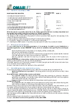
An automatic test is expected to check the seal of the hydraulic valves that participate in the cab block, at least 
once in 24 hours, and surely it happens if it is run when the car is automatically sent to the bottom floor. 
The sequence involves the activation of the solenoid ENR for a time of 5-10 s and, after a pause time between 
5 and 10 s, the solenoid activation ERS for 5-10 s. 
If, during the self-test detects an abnormal lowering of the cabin it must be taken out of service. 
And advisable, in case of re-leveling, repeat again once the test before putting the system out. The control 
panel, or the specific devices must have the possibility to easily perform the proof test and verification of the 
monitoring system. 
Involved signals: 


Содержание HEVOS HE250

Страница 1: ...D877 MGB Rev01 HE250 docx 1 50 OPERATING INSTRUCTIONS FOR HEVOS HE250 VALVE...

Страница 2: ...N 00 23 10 2019 Emission 01 26 11 2019 11 Remarks added to electric wiring scheme 01 26 11 2019 12 Updated App reference for WiFi connection 01 26 11 2019 16 24 Updated figure and commands description...

Страница 3: ...xing 17 2 15 Upward working cycle 18 2 16 Downward working cycle 20 2 17 Releveling 21 2 18 Rapture valve test DSP FC FP 21 2 19 Maximum pressure valve test DSP PP HP 22 2 20 Error condition 22 2 21 U...

Страница 4: ...and codes HEVOS HE250 valve unit 31 5 1 Parameters 31 5 2 Errors 36 6 Automatic reduction of travel times 39 6 1 Recovery leveling space 39 6 2 Reduction of starting time and maximum upward speed 39...

Страница 5: ...allation use and maintenance personnel The herewith instructions aim to permit the positive and safe execution of the installation operations starting up working control maintenance and possible repai...

Страница 6: ...ssary accessories and or required also check the correspondence of data on delivery and identification plates with those of the expected material 1 3 Storage In the installation waiting the group must...

Страница 7: ...nimum pressure clockwise increase anticlockwise decrease 26 Hand pump 27 Hand pump maximum pressure valve clockwise increase anticlockwise decrease 28 Hand pump non return valve 29 Hand pump air relea...

Страница 8: ...se increase anticlockwise decrease 26 Hand pump 27 Hand pump maximum pressure valve clockwise increase anticlockwise decrease 28 Hand pump non return valve 29 Hand pump air release screw 97 VNR valve...

Страница 9: ...27 Hand pump maximum pressure valve clockwise increase anticlockwise decrease 28 Hand pump non return valve 29 Hand pump air release screw 97 VNR valve block control throttle TF Flow meter TP1 Pressur...

Страница 10: ...10 50 D877 MGB Rev01 HE250 docx Plate mounting hole shape pattern Pump tube mounting hole pattern Weight 13kg Measures in mm...

Страница 11: ...operating LD31 LED Green ON Normal condition LD32 LED Blue ON Wi Fi module activated LD35 LED Orange ON SD memory activated OPTO ISOLATED DIGITAL INPUT Working voltage 20 60 VDC 100 mA CN6 UP Upward...

Страница 12: ...covery To save the parameters via SD CARD must use a Micro SD 2 to 16 GB already formatted FAT 32 Switch the RSW selector in position 7 the display will then show oc and will turn on ON Yellow LED LD3...

Страница 13: ...nt condition The second is to acquire the overload value with empty cabin In this case the P111 parameter must contain the value of the nominal laod rate and therefore will be entered in parameter P10...

Страница 14: ...deceleration change rate P312 Downward low speed m s fpm P313 Downward stopping distance m P314 Downward releveling acceleration distance m ft P315 Downward releveling speed m s fpm P316 Downward rel...

Страница 15: ...ver during operation the reference speeds in upward are limited to the value corresponding to the nominal pump flow rate set in P102 plus the percentage value set in P233 Downward starting conbination...

Страница 16: ...VALVE UNBLOCK SOLENOID VALVE ZERO VSC VALVE POSITION SENSOR TF FLOW SENSOR TP1 PRESSURE SENSOR TT TEMPERATURE SENSOR MPP VSC VALVE COMAMNDS TEPPER MOTOR D MPP STEPPER MOTOR CONTROL DRIVER RM STEPPER M...

Страница 17: ...D877 MGB Rev01 HE250 docx 17 50 2 14 SCH100 board dimensions and fixing Min space for SD and USB used N 7 Metallic spacers Board fixing Metal plate 1 5 mm for DIN 35 bracket...

Страница 18: ...tank at low pressure to allow a proper motor starting and avoid hit in the cabin caused by pump direct flow to piston UPWARD 4 8 MOTOR STARTING COMPLETED AND CABIN ACCELERATION DSP u1 Once finisch the...

Страница 19: ...esidual distance setted in the P458 parameter The calculation is reset when the board is off UPWARD 8 8 STOPPING DSP u5 Upon arrival at the stopping contact in the shaft it must turn off the upward UP...

Страница 20: ...speed signal P304 oppure P305 P306 P317 DOWNWARD 5 7 DECELERATION DSP d3 Upon arrival at the deceleration contact in the shaft turn off the high speed HSP signal or the SP3 signal if the parameter P4...

Страница 21: ...peed and the stopping distance 2 18 Rapture valve test DSP FC FP Block the system to exclude the possibility of travel Set the working selector RSW 3 DSP FC and then press S1 button until appear FP on...

Страница 22: ...Y if not performing a new maximim pressure test by pressing the button S1 as described above or a normal maneuver setting the selector RSW 0 Note As an alternative to the use of RSW switch you can act...

Страница 23: ...IAGRAM SCH001 Output ON Device Command ON M Motor input ENR ENR Solenoid valve input ERS ERS Solenoid valve input 2 UPWARD WORKING CYCLE DIAGRAM Motor Starting SCH001 Input ON b Upward deceleration co...

Страница 24: ...rs open it must activate the stop element interrupting any signal and command to the valve group In particular must be disconnected on SCH001 electronic card the inputs of ENR solenoid valves and ERS...

Страница 25: ...bin The device must operate the stop element i e interrupt signals to the valve group during the descent before the cab moves away from 200 mm from the floor In particular to activate the stop element...

Страница 26: ...el waiting for commands 2 4 ACTIVATION VALVE ENR DSP A1 Power input of only solenoid valve ENR The electronic board detects the necessary conditions and activates the output solenoid ENR which control...

Страница 27: ...azionare il dispositivo di emergenza manuale sino all intervento del ripescaggio If at the end of the relevelling the control panel repeats the test with the solenoid activation ERS DSP A3 cause as pr...

Страница 28: ...block of the the signal allows to check error detection from the electrical control panel Only with the parameter P461 0 the PNP1 signal switches according to the normal operation It is possible to c...

Страница 29: ...il tipo modello e i dati di certificazione oltre ad un QR code The valve group is applied a plaque showing the name and address of Manufacturer serial number the type model and the certification data...

Страница 30: ...t again At the end remember to close the gauge cut tap 4 2 Upward movement of the cab The displacement of the cabin upwards is possible by acting on the hand pump 26 through the appropriate actuating...

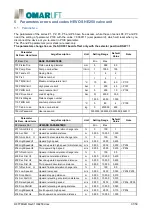
Страница 31: ...rd 0000000 9999999 0000000 8369111 Parameter Nr Desc Hand term Large Description Unit Setting Range Default Value Note P2 Upwars Par UPWARD PARAMETERS Min Max 201 AccStart U Upward initial acceleratio...

Страница 32: ...t D Downward stopping distance m 0 000 10 000 0 010 314 Acc Dist DR Downward releveling acceleration distance m 0 000 10 000 0 010 315 RelevSpeedD Downward releveling speed m s 0 000 0 300 0 050 P304...

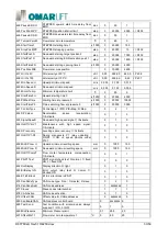
Страница 33: ...pressure 0 s 1000 0 20000 3000 451 ControlType Control type 1 PID PID Map 0 Map 0 2 1 452 SP Calcul Deceleration space recalculation 1 Activate 0 1 0 453 SignalSpeeD Downward high speed signal 1 Acti...

Страница 34: ...and input 0 1 524 OnOffI MAN Maintenance command input 0 1 525 OnOffI DHS Downward high speed optional command input 0 1 526 OnOffI PWM Motop pump started input 0 1 527 OnOffI HS1 Auxiliary speed 1 co...

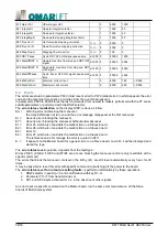
Страница 35: ...on 0 9999 712 Copy Master Master parameters duplication in the slave nodes 0 9999 713 Reset Err Errors reset master slave 0 9999 P8 Technic Par TECHNICAL PARAMETERS Min Max 851 Gain U4 Upward gain U4...

Страница 36: ...as follow EA Warning error not blocking the maneuver the relay ERR does not turn on and the error message disappears at the first maneuver Er Generic error blocking the maneuver Er Generic error bloc...

Страница 37: ...movement flow meter error Check if there are impediments to the flow 17 Er At the working anomaly of a solenoid valve Check starting input voltage ERS and ERN solenoid valves 18 Er At rest VSC zero s...

Страница 38: ...roblem 43 Er Stepper temperature warning MPP driver temperature attention level 44 Er Stepper overtemperature MPP driver thermal protection for valve ERS problem 45 Not used 46 Not used 47 Er CAN erro...

Страница 39: ...me and maximum upward speed The reduction of the total upstroke time reduces the consumption and oil heating The synchronization between the output contact AVV and digital input SFY electronic card al...

Страница 40: ...em set the low speed value and of the stop space so as to limit the stopping time to 1 1 5 s max according to the following formula Time s 2 x Stop space m Low speed m s es 2 x 0 02 m 0 05 m s 0 8 s 6...

Страница 41: ...er shut off valve 2 Release all pressure by manually adjusting the knob 17 Check that the level of pressure on the pressure gauge is next to zero equal to the valve setting 25 then after one minute re...

Страница 42: ...r plate is in the correct position and legible Also check the instructions of the emergency maneuvers the oil plate the wiring diagrams of the picture and the hydraulic diagram of the control unit 7 3...

Страница 43: ...cific stop contacts when micro leveling stopping To connect the auxiliary group contact the Technical Office UP Upward signal SCH001 board ML Micro leveling pump motor power supply PI Dependent speed...

Страница 44: ...address of the CAN node 1 to 127 of the corresponding card P 477 defines the total number of Slaves in the Multi specific valves system 1 to 7 P 478 defines the active status 1 or inactive 0 of the co...

Страница 45: ...crease 26 Hand pump 27 Hand pump maximum pressure valve clockwise increase anticlockwise decrease 28 Hand pump non return valve 29 Hand pump air release screw 97 VNR valve block control throttle TF Fl...

Страница 46: ...d in both terminator cards while it is to be let free in those intermediatedie The connections to the devices valve groups and the power of the board are the same as those of the single group Is possi...

Страница 47: ...E SENSOR MPP VSC VALVE COMAMND STEPPER MOTOR D MPP STEPPER MOTOR CONTROL DRIVER RM STEPPER MOTOR CONNECTION RELAY CN1 5 BOARD SENSOR INPUT CONNECTIONS CN6 8 BOARD SIGNALS INPUT CONNECTIONS CN9 16BOARD...

Страница 48: ...48 50 D877 MGB Rev01 HE250 docx 9 EU type certificate example...

Страница 49: ...D877 MGB Rev01 HE250 docx 49 50...

Страница 50: ...50 50 D877 MGB Rev01 HE250 docx OMARLIFT s r l Via F lli Kennedy 22 D 24060 Bagnatica BG ITALY Phone 39 035 689611 Fax 39 035 689671 Email info omarlift eu Web http www omarlift eu...

Отзывы: