


DMTA-10040-01EN, Rev. E, February 2018
Chapter 5
242
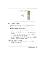
a)
Place the probe in a defect-free area near the tube’s support ring, and then
press the NULL foot switch.
b)
Slowly scan the support ring and check the signal.
If
AUTO MIX
was correctly performed, you will not see any signal from the
support ring (see Figure 5-170 on page 242).
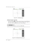
Figure 5
‑
170 The support ring signal after AUTO MIX
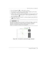
6.
Place the probe in a defect-free zone of the calibration standard near the small
thru-wall hole (1.3 mm [0.052 in.]), and then press the NULL foot switch.
7.
Slowly scan the 1.3 mm (0.052 in.) thru-wall hole only, pressing the ERASE foot
switch as required to clear the screen. When the hole signal is visible on the
NORTEC 600 screen, press the FREEZE key (
Содержание nortec 600
Страница 8: ...DMTA 10040 01EN Rev E February 2018 Table of Contents viii...
Страница 16: ...DMTA 10040 01EN Rev E February 2018 Labels and Symbols 6...
Страница 30: ...DMTA 10040 01EN Rev E February 2018 Introduction 20...
Страница 58: ...DMTA 10040 01EN Rev E February 2018 Chapter 1 48...
Страница 71: ...DMTA 10040 01EN Rev E February 2018 Software User Interface 61 Press the Return key to exit...
Страница 72: ...DMTA 10040 01EN Rev E February 2018 Chapter 2 62...
Страница 342: ...DMTA 10040 01EN Rev E February 2018 Chapter 7 332...
Страница 356: ...DMTA 10040 01EN Rev E February 2018 Appendix B 346...
Страница 366: ...DMTA 10040 01EN Rev E February 2018 List of Figures 356...
Страница 368: ...DMTA 10040 01EN Rev E February 2018 List of Tables 358...