


DMTA-20045-01EN, Rev. A, October 2012
HST-Lite Scanner 13
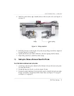
4.
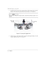
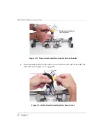
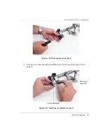
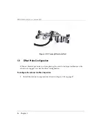
Install the probe and wedge assembly between the two yoke arms (see Figure 1-6
on page 13).
Figure 1-6 Wedge installed
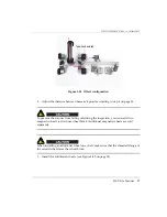
5.
Push the yoke arm in order to place the yoke arm guiding pin into the wedge side
hole (see Figure 1-6 on page 13).
6.
Tighten the thumbscrew until it holds the yoke arm tight against the holder.
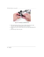
7.
Repeat the procedure to install the other wedge.
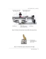
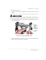
1.3
Setting the Distance Between Beam Exit Points
To set the distance between beam exit points
1.
According to the scan plan, determine the distance between the beam exit points
(for example, 40 mm).
2.
Divide the distance value by two (for example, 20 mm).
3.
Position the probe holders so their indicators point to the half value (for example,
20 mm) on the left- and right-hand side frame rulers (see Figure 1-7 on page 14
and Figure 1-8 on page 15).
Wedge
Yoke arm guiding
pin
Содержание HST-Lite
Страница 1: ...DMTA 20045 01EN Revision A October 2012 HST Lite Scanner User s Manual...
Страница 36: ...DMTA 20045 01EN Rev A October 2012 32 Chapter 3...
Страница 38: ...DMTA 20045 01EN Rev A October 2012 34 List of Figures...
Страница 40: ...DMTA 20045 01EN Rev A October 2012 36 List of Tables...
Страница 44: ...DMTA 20045 01EN Rev A October 2012 40 Index...


