Complete Teardown, Cleaning, and Reassembly of the Olympus BHSU/BHTU Reverse Nosepiece Assembly
Revision 3
Page 10 of 19
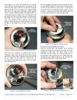
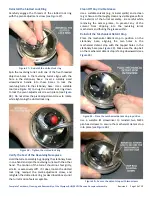
Remove the Center Pivot Bearing Ball
Use a tweezers or other suitable tool
to remove the ¼”
bearing ball from the center bore in the stationary base
(see
Figure 18
–
Remove the center-pivot bearing ball
Remove the Mechanical Detent Stop
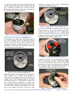
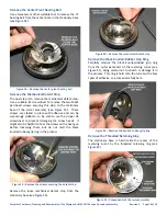
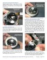
The next step is to remove the mechanical detent stop.
Use a suitable JIS screwdriver to remove the two M2x4
pan-head screws securing this stop to the stationary
base of the turret assembly (see
). These
screws are staked in place with adhesive and can be
surprisingly stubborn, so be sure to use the proper JIS
screwdriver to prevent damaging the screw heads. It
might also be helpful to heat the screws with a heat gun
before loosening them, but do not melt the black
knurled-rubber grip ring in the process.
Figure 19
–
Remove the screws securing the detent stop
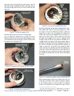
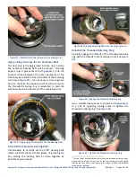
Remove the loose mechanical detent stop from the
stationary base (see
Figure 20
–
Remove the mechanical detent stop
Remove the Black Knurled-Rubber Grip Ring
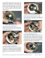
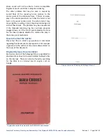
Carefully remove the black knurled-rubber grip ring
from the outer perimeter of the revolving turret (see
), being careful not to stretch or damage it in
the process. This ring is held onto the turret with a few
spots of adhesive, so proceed carefully here.
Figure 21
–
Remove the knurled-rubber grip ring
Remove the Threaded Retaining Ring
The stationary base is held inside the recess of the
revolving turret by the threaded retaining ring (see
Figure 22
–
Components of the turret assembly


