background image

DMTA-10022-01EN, Rev. C, January 2015

Basic Operation


55

5.2.1

Calibrating the Instrument

To make accurate measurements, you need to perform the following calibrations:

Material sound velocity calibration

Zero  calibration

The calibrations must be performed using a thick and a thin sample of precisely 
known thicknesses. The sample must be made of the same material as the parts to be 
inspected (see “Test Blocks” on page 58 for details on test blocks).

The following procedure is illustrated using a dual element probe and a five-step test 
block. Refer to “Calibration” on page 54 for more details on the calibration process.

To calibrate the instrument

1.

To perform the material sound velocity calibration using an instrument with or 
without the Waveform software option (see Figure 5-5 on page 56):

a)

Place a drop of couplant on the surface of the thick part of the test block.

b)

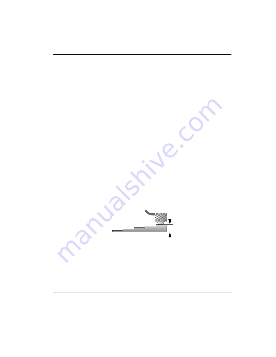
Couple the transducer to the thick part of the test block using moderate to 
firm pressure (see Figure 5-4 on page 55).
The waveform (optional) and the thickness reading appear on the screen.

c)

Press

 [CAL VEL]

.

d)

Once the thickness reading is stable, press 

[ENTER]

.

e)

Using the arrow keys, edit the thickness value to match the known thickness 
of the thick part of the test block.

Figure 5-4  Sound velocity calibration on a five-step test block — Thick part

12.7 mm (0.500 in.)

Содержание 45MG

Страница 1: ...nual This instruction manual contains essential information on how to use this Olympus product safely and effectively Before using this product thoroughly review this instruction manual Use the produc...

Страница 2: ...curacy of the information contained therein and corresponds to the version of the product manufactured prior to the date appearing on the title page There could however be some differences between the...

Страница 3: ...mpatibility 6 Repair and Modification 7 Safety Symbols 7 Safety Signal Words 8 Note Signal Words 8 Safety 9 Warnings 9 Battery Precautions 10 Equipment Disposal 11 WEEE Directive 11 China RoHS 11 EMC...

Страница 4: ...Text Parameters Using the Traditional Method 41 4 Initial Setup 43 4 1 Setting the User Interface Language and Other System Options 43 4 2 Selecting the Measurement Units 44 4 3 Setting the Clock 44...

Страница 5: ...ction Available Only with the Waveform Option 84 6 5 Single Element and High Resolution Option 86 6 5 1 Recalling Single Element Transducer Setups 87 6 5 2 Creating Custom Single Element Transducer Se...

Страница 6: ...ers 144 8 3 Configuring Communications 145 9 Using Advanced Gaging Features 149 9 1 Adjusting the Gain with Dual Element Transducers 149 9 2 Adjusting the Extended Blank with Dual Element Transducers...

Страница 7: ...Memory Card 190 11 3 3 Receiving Files from a Computer 192 11 4 Capturing Screen Images 193 11 4 1 Sending a Screen Capture to GageView 193 11 4 2 Sending a Screen Capture to the External microSD Car...

Страница 8: ...DMTA 10022 01EN Rev C January 2015 Table of Contents viii List of Tables 227 Index 229...

Страница 9: ...DB database DIAG diagnostic DIFF differential EFUP environment friendly use period ESS electronic stress screening EXT extended FRP fiber reinforced polymer GB gigabytes GRN green HDPE high density po...

Страница 10: ...on frequency PVC polyvinyl chloride RoHS restriction of hazardous substances SE single element STD standard SW software TDG time dependent gain TFT thin film transistor liquid crystal display technolo...

Страница 11: ...or all of the labels or symbols are missing or illegible please contact Olympus To avoid the risk of electric shock do not touch the inner conductor of the T R 1 and T R 2 connectors Up to 200 V can...

Страница 12: ...DMTA 10022 01EN Rev C January 2015 Labels and Symbols 2 Figure i 2 Labels attached to the back of the instrument Instruction label see Table 1 on page 3 Serial number labels two locations...

Страница 13: ...ols 3 Table 1 Label contents Serial number label Where yy last two digits of the production year nnnnn five digit non duplicated incrementing number representing the nth production unit of this produc...

Страница 14: ...applicable standards and has been registered with the Australian Communications and Media Authority ACMA for placement on the Australian market This symbol indicates the location of the membrane vent...

Страница 15: ...Do not use the 45MG for any purpose other than its intended use It must never be used to inspect or examine human or animal body parts Instruction Manual This instruction manual contains essential in...

Страница 16: ...p and operating procedures for all the instrument features The PDF file is available on the documentation CD P N 45MG MAN CD U8147024 that is shipped with the 45MG and can also be downloaded at www ol...

Страница 17: ...ent Safety Symbols The following safety symbols might appear on the instrument and in the instruction manual General warning symbol This symbol is used to alert the user to potential hazards All safet...

Страница 18: ...ed to could result in death or serious personal injury Do not proceed beyond a WARNING signal word until the indicated conditions are fully understood and met The CAUTION signal word indicates a poten...

Страница 19: ...Apparatus This instruction manual contains warnings and safety rules that must be observed by the user to ensure safe operation of the instrument and maintain it in safe condition Please read through...

Страница 20: ...ly When lithium metal batteries are used transportation of the batteries is regulated by the United Nations under the United Nations Recommendations on the Transport of Dangerous Goods It is expected...

Страница 21: ...People s Republic of China for the control of pollution by electronic information products EIP In accordance with European Directive 2012 19 EU on Waste Electrical and Electronic Equipment WEEE this...

Страница 22: ...ns not expressly approved by the party responsible for compliance could void the user s authority to operate the equipment This equipment has been tested and found to comply with the limits for a Clas...

Страница 23: ...select REGULATORY to display the REGULATORY screen see Figure i 3 on page 13 Figure i 3 The REGULATORY screen 3 Use the up and down arrow keys to scroll through the different REGULATORY screens 4 Pre...

Страница 24: ...intended solely as a teaching aid and shall not be used in any particular application without independent testing and or verification by the operator or the supervisor Such independent verification o...

Страница 25: ...easurement examples help the user become familiar with the instrument s capabilities This manual describes how to use the 45MG instrument s advanced features including the use of special transducers m...

Страница 26: ...DMTA 10022 01EN Rev C January 2015 Introduction 16...

Страница 27: ...of the 45MG continuously adjusts the receiver setup so that every measurement is optimized for reliability range sensitivity and accuracy An optional advanced internal datalogger can store up to 4750...

Страница 28: ...tures Single element transducers Echo to Echo and THRU COAT measurements High Penetration software for low frequency single element transducers A scan or waveform display Real time A scan waveform dis...

Страница 29: ...rotection rating Olympus cannot guarantee any level of ingress protection rating once the instrument seals have been manipulated You must use sound judgment and take proper precautions before exposing...

Страница 30: ...rs Figure 1 2 on page 20 illustrates the possible connections between the 45MG and external devices Figure 1 2 The 45MG connections Protective rubber boot Stand Strap rings at the four corners Color d...

Страница 31: ...page 21 Figure 1 3 The top end connectors The external microSD memory card slot is located behind the battery door see Figure 1 4 on page 21 Figure 1 4 The microSD connector behind the battery door U...

Страница 32: ...condary key function that can be activated by first pressing 2nd F Throughout this document references to a secondary function are written as follows 2nd F Primary Secondary For example the instructio...

Страница 33: ...ion Needs to be pressed prior to a key to activate the secondary function of the key Save Stores a measurement and optionally the corresponding waveform in the datalogger at the current ID number Free...

Страница 34: ...o the right Transducer recall Recalls default or custom transducer XDCR setups Reference value For some functions ex differential mode or thickness for velocity mode opens a screen allowing you to ent...

Страница 35: ...acter at the cursor position Do ZERO Compensates for transducer delay for dual element transducers and the M2008 transducer Setup menu Provides access to instrument parameters measurement system displ...

Страница 36: ...DMTA 10022 01EN Rev C January 2015 Chapter 1 26...

Страница 37: ...f power source used The 45MG can be powered by three AA size batteries by a computer through its USB connector or by a commercially available 5 volt USB power supply When using batteries the vertical...

Страница 38: ...AA size lithium batteries The 45MG does not recharge NiMH batteries To recharge the batteries you must use a commercially available external battery charger not included 2 2 1 Battery Operating Time T...

Страница 39: ...s Store batteries in a cool dry environment Avoid long term storage under sunlight or in other excessively hot places such as the trunk of an automobile 2 2 3 Replacing the Batteries The batteries are...

Страница 40: ...rtment cover 6 Remove the batteries 7 Insert three new batteries in the battery compartment making sure that you observe the correct polarity 8 Ensure that the gasket inside the battery compartment co...

Страница 41: ...ry 2015 Powering the 45MG 31 Figure 2 4 Selecting the battery type When replacing batteries make sure that they are full in order to ensure the accuracy of the estimated remaining battery life shown b...

Страница 42: ...DMTA 10022 01EN Rev C January 2015 Chapter 2 32...

Страница 43: ...ment screens The first screen see Figure 3 1 on page 33 displays when the Waveform option is not activated or when the Waveform option feature is turned off OR The second screen see Figure 3 2 on page...

Страница 44: ...echo The A scan also enables you to observe indications that may be too small to be measured by the instrument The ID bar available with the Datalogger option located at the top of the measurement scr...

Страница 45: ...capacity of 2 GB upon instrument start up Depending on the context and on the available functions and options various indicators and numeric values appear around the waveform display and around the m...

Страница 46: ...hat the returning signal from the transducer is beyond the upper receiver voltage limit the LOS indicator will be replaced by the SAT flag for indication of saturation This situation can normally be c...

Страница 47: ...nu example To select a menu or a submenu command 1 Press SETUP or FILE with the Datalogger option to display a menu 2 Use the and keys to highlight the desired menu command 3 If applicable and needed...

Страница 48: ...tom of the screen to indicate the keys required to select a parameter and edit its value To select a parameter and edit its value 1 Use the and keys to highlight the desired parameter 2 For parameters...

Страница 49: ...used see Editing Text Parameters Using the Virtual Keyboard on page 39 for details With the traditional method you must select each character from a hidden list of standard sorted letters numbers and...

Страница 50: ...x highlight either the left or right arrow button on the virtual keyboard and then press ENTER The cursor moves by one character position 5 When you need to delete a character a Move the cursor to the...

Страница 51: ...4 2 Editing Text Parameters Using the Traditional Method When the TEXT EDIT MODE is set to TRADITIONAL select each character from a hidden circular list of standard sorted letters numbers and special...

Страница 52: ...need to move the position of the cursor in the value text box use the or key 6 To insert a character at the cursor position press CAL ZERO The character at the cursor and all those to the right move o...

Страница 53: ...s pressed and notifies you of an alarm condition The beeper can be set to On or Off To save battery power while the instrument is not in use enable the inactive time function so that the instrument au...

Страница 54: ...et the measurement units 1 In the measurement screen press SETUP and then select MEAS 2 In the MEAS screen set UNIT TYPE to INCH or MILLIMETER 3 Press MEAS to return to the measurement screen 4 3 Sett...

Страница 55: ...re 4 3 on page 45 set the parameters to the current date and time 4 Set the desired DATE MODE and HOUR MODE and then select SET Figure 4 3 The CLOCK screen 4 4 Changing Display Settings The appearance...

Страница 56: ...allows you to activate or deactivate the zoom function see Activating the Zoom Function Available Only with the Waveform Option on page 84 for details RECTIFICATION allows you to select one of the re...

Страница 57: ...INDOOR or OUTDOOR 3 Press MEAS to return to the measurement screen Figure 4 5 Example of the indoor and the outdoor color schemes The indoor scheme gives the best visibility when the instrument is us...

Страница 58: ...centage level 3 Press MEAS to return to the measurement screen The 45MG uses a transflective color display that reflects ambient light and becomes brighter in direct light In brighter ambient conditio...

Страница 59: ...ents in order to help limit transducer contact time or for applications where the transducer is scanned over an area in order to determine the minimum thickness The 45MG automatically uses the fastest...

Страница 60: ...n of the last digit is not required or where extremely rough outside or inside surfaces make the last thickness display digit unreliable The Single Element including High Resolution software option P...

Страница 61: ...supplied with the instrument With dual element transducers you need to perform a transducer zero compensation For Single Element or High Penetration software options and single element transducers yo...

Страница 62: ...r the Do message appears in the measurement screen see Figure 5 2 on page 52 Figure 5 2 Initial screen with a standard D79X dual element transducer 3 For dual element transducers perform the transduce...

Страница 63: ...the example shown in Figure 5 3 on page 53 highlight the setup in the list of available default setups for the transducer that you are using Figure 5 3 Selecting a default single element transducer s...

Страница 64: ...nificantly see Setting Up the Transducer on page 51 and Transducer Zero Compensation on page 58 Material sound velocity calibration CAL VEL Perform a velocity calibration using a thick test block of t...

Страница 65: ...page 54 for more details on the calibration process To calibrate the instrument 1 To perform the material sound velocity calibration using an instrument with or without the Waveform software option se...

Страница 66: ...plant on the surface of the thin part of the test block b Couple the transducer to the thin part of the test block see Figure 5 6 on page 56 and then press CAL ZERO c Once the thickness reading is sta...

Страница 67: ...alue Instead the instrument retains the previous value When the 45MG detects an error in the calibration procedure it successively displays the following messages in the help text bar before returning...

Страница 68: ...own thicknesses Has one part as thin as the thinnest section of the parts to be tested in order to perform the zero calibration The surface condition should be similar to that of the tested parts Roug...

Страница 69: ...D790 SM D791 RM or D797 SM for high temperature applications thereby minimizing the frequency of the zero compensation The D790 SM and D791 RM can also be used for general purpose applications 5 2 4...

Страница 70: ...nd F CAL VEL VEL 2 In the VELOCITY screen see Figure 5 9 on page 60 use the arrow keys to edit the velocity to the known value Figure 5 9 Entering a known material sound velocity 3 Press MEAS to retur...

Страница 71: ...ned when both the front and back surfaces of the test piece are smooth When the contact surface is rough the minimum thickness that can be measured will be increased as a result of sound reverberating...

Страница 72: ...alse readings Taper or eccentricity If the contact surface or back surface of the test piece is tapered or eccentric with respect to the other the return echo is distorted due to the variation of the...

Страница 73: ...by air or a liquid both of which have a lower acoustic impedance than metals ceramics or plastics However in some specialized cases such as measurement of glass or plastic liners over metal or copper...

Страница 74: ...ase Special couplants are required for high temperature applications 2 Using moderate to firm pressure couple the tip of the transducer to the surface of the test material and keep the transducer as f...

Страница 75: ...t a thickness measurement location ID Each time you press SAVE the displayed value is saved to the active file at the current ID The ID is automatically incremented for the next measurement When you p...

Страница 76: ...t the current ID the new value overwrites the old thickness reading unless the overwrite protection is enabled see Setting the ID Overwrite Protection on page 115 When the ID increment reaches the end...

Страница 77: ...measurements in Echo to Echo and THRU COAT modes These features are used to measure the remaining metal thickness when the material is painted coated Note Manual Echo to Echo is only available when th...

Страница 78: ...only on that specific 45MG unit A single option key is capable of activating one several or all software options Single Element including High Resolution see Measurements with Optional THRU COAT D790...

Страница 79: ...options where the check mark indicates that the option is activated Figure 6 1 The OPTIONS screen 3 To purchase one or more software options contact your local Olympus representative and provide the a...

Страница 80: ...s to the left of the thickness reading and a triangular echo detection marker appears at the back wall echo below the waveform display see Figure 6 2 on page 70 Figure 6 2 Measuring with the standard...

Страница 81: ...anking parameters can also be manually adjusted in this mode This mode is useful when material conditions produce noisy signals that could render the automatic mode less effective The DE MEtoE indicat...

Страница 82: ...n be used with the echo to echo modes The internal datalogger recognizes all necessary echo to echo information and saves it in order to upload and download thickness waveform and setup data It is not...

Страница 83: ...part of the test block 6 2 1 Blanking Adjustments in Manual Echo to Echo Detection Mode The 45MG offers two blanking functions to help detect valid echoes in situations where material conditions gene...

Страница 84: ...s 3 Use the and keys to select either the EXT BLANK or the E1 BLANK parameter 4 Use the and keys to adjust the value to exclude unwanted peaks and to detect the desired echoes 6 2 2 Dual Element Trans...

Страница 85: ...7 in helps eliminate the possibility of this error In some cases the second or third back wall echo is smaller in amplitude than subsequent echoes which causes the instrument to give a double or trip...

Страница 86: ...THRU COAT function to work properly the thickness of the coating or paint must be at least 0 125 mm 0 005 in thick The maximum coating paint thickness that THRU COAT can measure is dependent on the ty...

Страница 87: ...procedure below The difference is that towards the end of the procedure you can press CAL VEL a second time to calibrate the coating thickness measurement on a sample with an accurately known coating...

Страница 88: ...dit the calibrated metal sound velocity Pressing 2nd F CAL VEL VEL again opens the VELOCITY screen for the calibrated sound velocity through the coating 6 4 Waveform Software Option The live Waveform...

Страница 89: ...delay Auto Zoom This mode automatically adjusts the range and delay so that the measured echo is always on screen The waveform rectification Enables the user to switch the waveform between Full wave H...

Страница 90: ...The rectification mode determines the way in which the ultrasonic echoes are represented on the waveform display see Figure 6 9 on page 81 The rectification mode does not affect the thickness measure...

Страница 91: ...t overall representation of position and magnitude for most thickness measurement applications FULL is the default mode for dual element transducers HALF NEG indicator This mode shows negative wavefor...

Страница 92: ...e range of the waveform display see Figure 6 11 on page 83 is the distance spanned by the horizontal axis of the waveform display The left end of the horizontal axis the delay is generally set to zero...

Страница 93: ...pplication The range setting affects only the waveform display It is possible to make measurements even when the display range does not show the detected echo from which the thickness is measured The...

Страница 94: ...echoes can be seen in greater detail To adjust the delay value In the measurement screen press the and keys to adjust the delay When the GAIN WAVE ADJ parameters are active the range and delay become...

Страница 95: ...echo on the screen see Figure 6 12 on page 85 Figure 6 12 Comparing the normal and zoomed display in mode 1 The zoom with single element transducers in mode 2 adjusts the waveform range and delay so...

Страница 96: ...F 6 5 Single Element and High Resolution Option The optional Single Element High Resolution software allows the 45MG to use single element direct contact delay line and immersion transducers This enab...

Страница 97: ...lay thickness readings with a high resolution of 0 001 mm or 0 0001 in High resolution is not available for all transducers and measurement modes and is also limited to the maximum thickness Although...

Страница 98: ...temperature changes in the delay line To use the high penetration software option with the M2008 transducer 1 Ensure that the high penetration software option is activated see Activating Software Opt...

Страница 99: ...ve file appears in the ID bar above the menu see Figure 6 15 on page 89 Figure 6 15 The active file name appears in the ID bar The file also contains header parameters that can be defined to better de...

Страница 100: ...ions Table 6 on page 91 describes the additional data stored with each thickness measurement and with each waveform Measurement data Organized by predefined IDs arranged by file types Data File Types...

Страница 101: ...e on page 92 perform a number of file operations see Performing File Operations on page 105 and perform data operations see Setting the ID Overwrite Protection on page 115 Table 6 Additional informati...

Страница 102: ...he INSPECTOR ID optionally enter an identification of the inspector d In the LOCATION NOTE parameter optionally enter an identification of where the measurements are performed e Select the appropriate...

Страница 103: ...F or 2nd F to scroll between parameters on the screen 6 7 2 1 Data File Types You can create a data file using one of the following five data file types Incremental Sequential Sequential with Custom...

Страница 104: ...transition only after incrementing the character to the left Increments letters from A B C Z Makes the Z to A transition only after incrementing the character to the left When an ID cannot be incremen...

Страница 105: ...details on the first parameters 2 In the CREATE screen see Figure 6 18 on page 95 a Enter the START ID value b Select CREATE Figure 6 18 The CREATE screen for the incremental data file type ABC ABC AB...

Страница 106: ...ples in Table 8 on page 96 To create a sequential data file 1 In the measurement screen press FILE and then select CREATE see Creating a Data File on page 92 for details on the first parameters 2 At t...

Страница 107: ...addition multiple thickness readings per ID number location are assigned using the assigned custom points Use the sequential with custom point data file type when you want for example to measure along...

Страница 108: ...h custom points 1 In the measurement screen press FILE and then select CREATE see Creating a Data File on page 92 for details on the first parameters 2 At the bottom of the CREATE screen select CONTIN...

Страница 109: ...point the other dimension increments from its first to last value This continues until the ID number that refers to the last column and the last row is reached You have the option to select whether t...

Страница 110: ...dentical parts Alternatively the rows and columns of a grid may refer to a two dimensional map of measurement points on the surface of one part In this case a different grid is created for each part s...

Страница 111: ...ating a Data File on page 92 for details on the first parameters 2 At the bottom of the CREATE screen select CONTINUE 3 In the second page of the CREATE screen see Figure 6 24 on page 102 a Enter the...

Страница 112: ...file type The 45MG has the capability to add a row or a column and to change the incrementation direction after a grid file is created see Editing a File on page 108 for details 6 7 2 6 Boiler Data F...

Страница 113: ...urement screen press FILE and then select CREATE see Creating a Data File on page 92 for details on the first parameters 2 At the bottom of the CREATE screen select CONTINUE 3 In the second page of th...

Страница 114: ...in the file see step 2 f in Creating a Data File on page 92 Table 11 on page 104 describes the available file data mode options Only one type of data can be stored in a file Table 11 File data mode s...

Страница 115: ...med see Figure 6 26 on page 106 The following sections describe how to perform the operations Datalogger files are stored in the internal microSD memory card and these files can be imported exported f...

Страница 116: ...EN screen see Figure 6 27 on page 107 a In SORT BY select the order in which the files appearing on screen are sorted by NAME or by DATE CREATED b In the list of files select the file you want to open...

Страница 117: ...VIEW and then press ENTER 2 In the OPEN screen choose SORT BY and then select NAME or DATE CREATED to select how files are displayed on screen 3 In the list of files select the file you want to review...

Страница 118: ...he COPY screen see Figure 6 28 on page 108 a In the list select the source file b In COPY NAME enter the file name for the destination file c Set COPY THICKNESS DATA to YES when you also want to copy...

Страница 119: ...e measurement screen press FILE and then select EDIT 2 In the EDIT screen see Figure 6 29 on page 110 a In the list select the file you want to edit When scrolling through the file names a descriptive...

Страница 120: ...igure 6 30 on page 111 a Increase the END COLUMN and END ROW values as needed These values cannot be decreased b If needed change the INC 1ST BY value c Change the incrementing direction of rows colum...

Страница 121: ...deleted it is not possible to recover any information previously contained in that file To delete a file stored in the 45MG 1 In the measurement screen press FILE and then select DELETE 2 In the DELE...

Страница 122: ...are not delete protected 6 7 4 6 Deleting a Range of IDs It is possible to delete a range of IDs in the active file by using the clear memory function This function deletes both the data and the ID nu...

Страница 123: ...all the files stored in the 45MG Using the internal memory reset or master reset erases all files and the data contained in those files The deleted files and the data they contain cannot be recovered...

Страница 124: ...arning message when resetting measurements 6 7 4 8 Viewing the Memory Status To view the memory status 1 Press FILE select MEMORY and then press ENTER to display the MEMORY status screen see Figure 6...

Страница 125: ...e ID overwrite protection message To set the ID overwrite protection 1 In the measurement screen press SETUP and then select MEAS 2 In the MEAS screen set ID OVERWRITE PROT to ON or OFF 3 Press MEAS t...

Страница 126: ...ent ID location to any location that already exists in the data file for the purpose of editing that ID location 6 7 6 1 Reviewing Stored Data and Changing the Active ID The ID review screen is used t...

Страница 127: ...ress MEAS to return to the measurement screen with the new active ID 6 7 6 2 Editing the ID The ID can be edited as follows Change the active ID to quickly jump to an existing ID This is useful when y...

Страница 128: ...5 Press MEAS to return to the measurement screen with the new active ID 6 When the edited ID is not in the database the help text bar message shown in Figure 6 38 on page 119 appears Select INSERT to...

Страница 129: ...anging the Active ID on page 117 and then press MEAS 3 Press SAVE when not getting a reading to save and then erase the single reading ID The displayed ID changes to the next ID in the sequence The ea...

Страница 130: ...ompare them The first file contains the previous inspection data and the second file contains the current inspection data The report indicates the maximum wall loss and any area of greater wall thickn...

Страница 131: ...39 The FILE SUMMARY report screen Figure 6 40 The FILE SUMMARY report result screen c Select CANCEL to return to the measurement screen or NEW REPORT to generate another report 4 In the MIN MAX SUMMA...

Страница 132: ...urement screen or NEW REPORT to generate another report 5 In the FILE COMPARISON screen see Figure 6 42 on page 123 a In the upper list select the reference file you want to use in the comparison b In...

Страница 133: ...s location list and the maximum wall growth location list e Select CANCEL to return to the measurement screen or NEW REPORT to generate another report 6 In the ALARM SUMMARY screen a Select the file f...

Страница 134: ...ect CANCEL to return to the measurement screen or NEW REPORT to generate another report 7 In the MIN REVIEW screen a Select the file for which you want to generate the report b Select REPORT The MIN R...

Страница 135: ...the selected minimum ID in the file see Figure 6 46 on page 125 Figure 6 46 Returning to the measurement screen d Couple the probe back to the minimum ID location to verify the thickness and then pres...

Страница 136: ...DMTA 10022 01EN Rev C January 2015 Chapter 6 126...

Страница 137: ...thickness operation they can make the gage a more versatile instrument 7 1 Activating and Configuring a Differential Mode The 45MG includes differential modes that can be used to easily compare the ac...

Страница 138: ...ect one of the three differential modes NORMAL Shows the actual thickness along with the difference between the actual thickness measurement and the REF VALUE entered RATIO Shows the actual thickness...

Страница 139: ...r REDUCTION RT 3 Press MEAS to return to the measurement screen with the displayed differential value 7 2 Using the Minimum Maximum or Min Max Thickness Mode The minimum maximum or min max thickness m...

Страница 140: ...fastest display update rate is automatically activated when entering the minimum or maximum thickness mode When leaving the mode the display update rate is restored to its previous state Active readi...

Страница 141: ...MAX reading also resets the value 7 3 Preventing False Minimum Maximum Thickness Readings A false minimum or maximum reading can occur when you lift the transducer from the test piece This is due to...

Страница 142: ...e and alarm indicator only appear in color when the indoor color scheme is active see Color Schemes on page 47 to change the color scheme Figure 7 4 Example of a HIGH alarm indicator shown with the Wa...

Страница 143: ...RT alarms are only available when the B scan or reduction rate DIFF mode are activated These functions must be turned on first before the B SCAN and REDUCTION RT alarms can be activated B SCAN The B...

Страница 144: ...LLOW ALARM and high RED ALARM limits following which the instrument displays see Figure 7 6 on page 134 The RED indicator for reduction rates that are greater than or equal to the RED ALARM value The...

Страница 145: ...he B SCAN option only appears when the B scan mode is active see Using the B Scan on page 156 The REDUCTION RT option only appears when the active file is configured with the FILE DATA MODE parameter...

Страница 146: ...ked Calibration with CAL VEL and CAL ZERO Gain and waveform adjustments with GAIN WAVE ADJ Transducer setup recall with XDCR RECALL Setup menu accessed with SETUP File menu or datalogger operations ac...

Страница 147: ...e 7 9 on page 137 enter your password using up to eight alphanumeric characters If you forget your password you can unlock the instrument and deactivate the password by entering the master password OL...

Страница 148: ...ng the Measurement or Optional Waveform Pressing FREEZE stops updating the display and optional waveform and keeps the waveform and thickness on the display even if you move or uncouple the transducer...

Страница 149: ...9 To freeze the waveform and thickness display 1 Press FREEZE while making a measurement 2 Press FREEZE again to unfreeze the waveform and the thickness display Pressing MEAS or SAVE when the Datalogg...

Страница 150: ...DMTA 10022 01EN Rev C January 2015 Chapter 7 140...

Страница 151: ...ng Measurement Parameters The MEAS setup is the most commonly used setup menu screen and is used to access global parameters concerning the instrument measurement features To configure measurement par...

Страница 152: ...e instrument from the following options STANDARD Measure to the first back wall echo AUTO ECHO TO ECHO optional Measure between the successive back wall echoes MANUAL ECHO TO ECHO optional with the Wa...

Страница 153: ...indicating the stability of the averaged reading 9 Set ID OVERWRITE PROT to ON with the Datalogger option only if you want to see a confirmation message in the help bar when attempting to save a measu...

Страница 154: ...Interface Language and Other System Options on page 43 for details 3 Set INACTIVE TIME to ON or OFF see Setting the User Interface Language and Other System Options on page 43 for details 4 In the LA...

Страница 155: ...Screen Capture to the External microSD Card on page 195 for details 10 Press MEAS to return to the measurement screen 8 3 Configuring Communications The 45MG features a USB port that can be used to co...

Страница 156: ...output the B scan data when communicating with the GageView interface program Set it to OFF when communicating with other interface programs that do not support the B scan data This parameter only app...

Страница 157: ...DMTA 10022 01EN Rev C January 2015 Configuring the Instrument 147 Figure 8 3 The COMM screen...

Страница 158: ...DMTA 10022 01EN Rev C January 2015 Chapter 8 148...

Страница 159: ...Gain with Dual Element Transducers With D79X series dual element transducers you can manually adjust the gain by pressing GAIN WAVE ADJ The 45MG offers two types of gain adjustments The standard feat...

Страница 160: ...eiver output enabling you to readily observe gain changes To be processed for thickness calculation the peak amplitude of measured echoes must be at or above the threshold To view restore or change th...

Страница 161: ...tically adjusted echo height mode The default automatic gain mode is indicated by a blank Gain field 9 2 Adjusting the Extended Blank with Dual Element Transducers Olympus recommends using the extende...

Страница 162: ...ut initially its value is zero The gage remains in the measurement screen 3 Use the or keys respectively to increase or decrease the blank value until early unwanted echoes are excluded from detection...

Страница 163: ...make an accurate detection 9 3 B Scan A B scan is a cross sectional image of thickness readings The 45MG can acquire and display B scan data see Figure 9 3 on page 153 When you activate the B scan th...

Страница 164: ...direction to match the direction of transducer movement A scan direction arrow appears below the left corner of the B scan display to indicate the transducer scan direction see Figure 9 5 on page 155...

Страница 165: ...s readings are displayed when FREEZE is pressed while a B scan is active SHOW MINIMUM Displays the thickness reading for the minimum reading collected during the scan SHOW MAXIMUM Displays the thickne...

Страница 166: ...n and the review marker on the minimum or maximum thickness Figure 9 6 B scan freeze review elements MAX THK MODE Determines the vertical scale of the B scan 9 3 1 Using the B Scan The following proce...

Страница 167: ...values and turn the visual and audible alarm functions ON and OFF The B scan alarm mode is similar to the standard alarm mode see Using Alarms on page 131 except that the alarm lines are shown in the...

Страница 168: ...ss SAVE to save the thickness value for the review marker position to the datalogger To save the minimum or maximum thickness reading for a frozen B scan 1 Set B SCAN FREEZE MODE to SHOW MINIMUM or SH...

Страница 169: ...the B scan without saving 9 4 DB Grid The database grid DB grid is a table representation of 2 D data This representation enables you to move freely in any direction on a grid rather than follow a pre...

Страница 170: ...asurement screen press SETUP and then select DB GRID 2 In the DB GRID screen see Figure 9 8 on page 160 perform the following steps Figure 9 8 Changing DB grid parameters 3 Set DB GRID ENABLE to ON to...

Страница 171: ...e thickness value in the data cell see Figure 9 7 on page 159 The available options are NONE No data cell flag appears MIN MAX m indicates a minimum thickness M indicates a maximum thickness ALARM L i...

Страница 172: ...ctivating and Configuring the DB Grid on page 160 2 In the measurement screen press 2nd F FILE ID 3 In the ID review screen see Figure 9 11 on page 162 a Use the and keys to highlight the desired grid...

Страница 173: ...number in the sequence The new ID number is indicated on the ID bar and its cell is highlighted in the grid If the ID number cannot be updated a long beep sound is emitted and the instrument displays...

Страница 174: ...to move to the desired shaded grid cell 3 Press ENTER to change the grid to a linear view following which the inserted or appended ID number is displayed see Figure 9 13 on page 164 Figure 9 13 Exampl...

Страница 175: ...ups by selecting a previously saved setup 10 1 Creating a Custom Setup for a Single Element Transducer A custom setup should be created when the measurement requirements of a particular application ar...

Страница 176: ...s 2nd F FREEZE XDCR RECALL 3 In the menu select the CUSTOM SINGLE ELEMENT 4 In the CUSTOM SINGLE ELEMENT screen select the desired custom setup location SE USER n in which you want to save the custom...

Страница 177: ...material for this transducer see Calibrating the Instrument on page 55 g If needed increase the PULSER POWER to increase the ultrasound wave penetration in the material Reduce the value for better ne...

Страница 178: ...dual waveform parameters 1 Ensure that a single element transducer is connected to the 45MG 2 In the measurement screen press GAIN WAVE ADJ The waveform adjustment parameter appears above the thicknes...

Страница 179: ...details INIT GAIN see Initial Gain on page 175 for details MAX GAIN see Maximum Gain on page 174 for details PULSER POWER see Pulser Power on page 172 for details PROBE TYPE MEAS TYPE see step 5 c in...

Страница 180: ...line or an immersion transducer see Figure 10 4 on page 170 Figure 10 4 Mode 2 detection example Mode 3 Uses a delay line or an immersion transducer to measure the time of flight between one back wal...

Страница 181: ...back wall echo is irregular and contains several negative or positive peaks that are close in amplitude In such cases the thickness reading can fluctuate as the gage switches detection from one peak...

Страница 182: ...ion at the expense of a lower near surface resolution especially in mode 1 Inversely lower voltages may provide better near surface resolution at the expense of a lower penetration For most applicatio...

Страница 183: ...atic gain control AGC see Configuring Measurement Parameters on page 141 for details on how to activate the AGC or the time dependent gain TDG functions to automatically adjust receiver gain to an opt...

Страница 184: ...ed to amplify echoes that are further out in time In general for any given application the maximum gain should be set high enough that all echoes of interest are detected The maximum available receive...

Страница 185: ...echoes that are close to the main bang or interface echoes Starts at time zero and extends to The main bang blank in mode 1 The end of the interface blank in modes 2 and 3 10 6 3 TDG Slope The TDG slo...

Страница 186: ...gain level see Figure 10 9 on page 176 When the main bang blank is too short the instrument hangs up on the excitation pulse and readings are not possible When the main bang blank is too long the mini...

Страница 187: ...al begins at the end of the main bang blank The echo window ends at x s following the main bang in mode 1 or at x s following the interface blank in mode 2 and mode 3 In mode 1 you can usually set the...

Страница 188: ...cho window must be set ahead of the second interface echo in order to prevent an incorrect detection which in turn determines a maximum measurable thickness In applications involving mode 2 and mode 3...

Страница 189: ...eak Positive and negative polarity refer to processed echoes displayed on the waveform display see Figure 10 13 on page 179 To measure thicknesses with the highest accuracy it is important for the 45M...

Страница 190: ...when measuring material of low acoustic impedance bonded to a material of high impedance such as plastic or rubber over metal where the echo is phase reversed Not applicable Mode 2 using delay line o...

Страница 191: ...interface blank selects which pair of back wall echoes are measured see Figure 10 15 on page 182 In most conditions the interface blank would be set just short of the first back wall echo However as...

Страница 192: ...lank or dead zone up to 20 s long following the leading edge of the first detected back wall echo in order to prevent detection of trailing lobes or cycles of that echo and the resulting gage hang up...

Страница 193: ...eters it is possible to store the settings for quick and easy recall The 45MG can store up to 35 custom setups in its internal memory To save setup parameters 1 Make the appropriate changes to the wav...

Страница 194: ...pressing MEAS This process is adequate for typical setups that are changed infrequently However when it is necessary to change between two or more custom setups on a more frequent basis use the quick...

Страница 195: ...recall the first custom single element transducer setup OR Press 2nd F to recall the second custom single element transducer setup OR Press 2nd F to recall the third custom single element transducer s...

Страница 196: ...DMTA 10022 01EN Rev C January 2015 Chapter 10 186...

Страница 197: ...such as the 45MG GageView provides the capability to create inspection database files upload and download data files and generate reports Olympus recommends using GageView to communicate with the 45MG...

Страница 198: ...cable to the USB client connector on the top of the 45MG and connect the other end to a USB port of the computer see Figure 11 1 on page 188 Figure 11 1 Connecting the 45MG to a computer The first tim...

Страница 199: ...Option Only The 45MG has the ability to export files from the internal memory to the external microSD memory card Files can be exported in CSV comma separated variables text space delimited or survey...

Страница 200: ...n various Windows based programs 5 Select EXPORT The selected file is created in the following folder on the external microSD memory card OlympusNDT 45MG Transfer The instrument then automatically ret...

Страница 201: ...rn the 45MG off and then back on so that it recognizes the presence of the memory card 4 In the measurement screen press FILE and then select IMPORT 5 In the IMPORT screen see Figure 11 3 on page 191...

Страница 202: ...to the instrument This externally created sequence can guide you through the prescribed measurement location path The ID sequence created in the computer must have setup information The setup can be...

Страница 203: ...for information on how to install and use GageView To send a screen capture to GageView 1 Set the USB communication parameters and then connect the 45MG to the computer see Setting Up USB Communicatio...

Страница 204: ...menu select Device Tools b In the Device Tools dialog box see Figure 11 5 on page 195 select Screen Capture and then click Receive The screen image appears once the data transfer is complete c Click...

Страница 205: ...the file in any program capable of viewing bitmap bmp files To send a screen capture to the external microSD card 1 Ensure that a microSD memory card is inserted in its slot under the battery door of...

Страница 206: ...lder on the card to the desired folder on the computer 11 5 Resetting the Communication Parameters The communication reset function quickly returns communication parameters to their factory default va...

Страница 207: ...DMTA 10022 01EN Rev C January 2015 Managing Communications and Data Transfer 197 Figure 11 6 Selecting COMMUNICATION RESET...

Страница 208: ...DMTA 10022 01EN Rev C January 2015 Chapter 11 198...

Страница 209: ...ithstand normal field use However as with any electronic instrument damage is possible if the instrument is not handled with adequate care Observe the following instructions in particular Never press...

Страница 210: ...ere is a risk that a heavy object could be placed on the cable Never remove a transducer from the gage by pulling on the cable pull on the molded connector only Never tie a knot in the transducer cabl...

Страница 211: ...0 A M in the 12 hour format COMMUNICATION RESET Changes the communication settings to the default factory values listed in Table 15 on page 202 Table 14 Measurement default settings Parameter Default...

Страница 212: ...f the 45MG To activate a reset function 1 In the measurement screen press SETUP and then select RESETS 2 In the RESETS screen see Figure 12 1 on page 203 a In the RESETS list highlight the desired res...

Страница 213: ...lympus internal testing procedures during the manufacturing process The available tests are as follows Keypad test Video test Internal microSD card test Pass or Fail External microSD card test Pass or...

Страница 214: ...MEAS to start the video test The display shows vertical color strips Any problems with the display show up as a disruption of the pattern b Press ENTER to terminate the video test 6 When INTERNAL SD...

Страница 215: ...values indicates that the delay line wear is not the same for each element A missing value indicates that a cable is broken or that the element is not functioning c Take note of the calculated ZERO V...

Страница 216: ...een 12 7 Viewing the Instrument Status The STATUS screen lists important information about the instrument The status screen displays the following information Current instrument internal temperature C...

Страница 217: ...h the operating procedure but certain messages might indicate a physical problem with the gage itself If you do not understand an error message contact Olympus for assistance 12 9 Resolving Battery Pr...

Страница 218: ...e requires service try the master reset The echo is too low in amplitude to be detected Try increasing the gain Strong echoes no measurements The echo may be in a blank area of the waveform and cannot...

Страница 219: ...set to 20 Alkaline nonrechargeable 20 21 hours NiMH externally rechargeable 22 23 hours Lithium nonrechargeable 35 36 hours Operating temperature 10 C to 50 C 14 F to 122 F Battery storage temperatur...

Страница 220: ...g out 3 5 ns typical pulse width dependent Pulse duration Adjustable to probe frequency Table 20 Receiver EN15317 specifications Parameter Value Gain control Automatic or manual 40 dB to 99 dB Frequen...

Страница 221: ...IV Transit Drop Table 23 Measurement specifications Parameter Value Measurement modes Standard dual element Time between excitation pulse and first back wall echo using dual element transducer Dual Ec...

Страница 222: ...File name length 1 to 32 characters File formats Incremental Sequential defined by starting and ending ID number Sequential with custom points 2 D grid Boiler External memory card microSD memory card...

Страница 223: ...o 12 5 mm 0 025 in to 0 500 in DEFM2 5 0 M206 M206 Steel 1 25 mm to 19 00 mm 0 050 in to 0 750 in DEFP2 5 0 M206 M206 Plastic 1 mm to 12 5 mm 0 040 in to 0 500 in DEFM2 2 25 M207 M207 Steel 2 00 mm to...

Страница 224: ...detect gate which begins at end of MB main bang blank in mode 1 or interface echo in modes 2 and 3 The value reported for the end of the echo window is relative to the main bang 0 ns to 224 71 s 55 n...

Страница 225: ...es the transducer type and optimizes the gage for that transducer Non Olympus transducers might work but performance is not guaranteed The following transducers are supported D790 D790 SM D791 D791 RM...

Страница 226: ...DMTA 10022 01EN Rev C January 2015 Appendix A 216...

Страница 227: ...ure Therefore for maximum accuracy when establishing the sound velocity in a given material first test a sample of the material Table 28 Sound velocities in common materials Material V m s V in s Acry...

Страница 228: ...w York D Van Nostrand Co 1958 Papadakis E P Panametrics unpublished notes 1972 Polyamide slow 2200 0 087 Nylon fast 2600 0 102 Polyethylene high density HDPE 2460 0 097 Polyethylene low density LDPE 2...

Страница 229: ...WF U8147019 Optional Single Element including High Resolution installed in units using an activation code 45MG SE U8147022 Optional Single Element High Penetration software installed in units using an...

Страница 230: ...38 C 1000 F 0 06 l 2 oz Couplant E 2 U8770274 Medium temperature up to 260 C 500 F 0 06 l 2 oz Couplant F 2 U8770141 Table 33 Test blocks Description Part number 5 step 1018 steel English units 0 100...

Страница 231: ...s 221 2 step 303 stainless steel Metric units 1 mm 15 mm 2218M U8880024 2 step 303 stainless steel English units 0 200 in 1 500 in 2219E U8880026 2 step 303 stainless steel Metric units 5 mm 30 mm 221...

Страница 232: ...DMTA 10022 01EN Rev C January 2015 Appendix C 222...

Страница 233: ...ry compartment 29 Figure 2 4 Selecting the battery type 31 Figure 3 1 The measurement screen No waveform enabled 33 Figure 3 2 The measurement screen Waveform option enabled 34 Figure 3 3 The ID bar 3...

Страница 234: ...6 6 Opening the THRU COAT setup dialog box 77 Figure 6 7 Standard display 79 Figure 6 8 Waveform display 80 Figure 6 9 Examples of the rectification modes 81 Figure 6 10 Examples of waveform trace mo...

Страница 235: ...ential mode shown with Waveform option activated 127 Figure 7 2 The DIFF screen 129 Figure 7 3 Displaying the minimum and or maximum thickness shown with the Waveform option activated 130 Figure 7 4 E...

Страница 236: ...nk position for mode 2 and mode 3 177 Figure 10 11 Echo window setting for mode 1 178 Figure 10 12 Echo window setting for mode 2 and mode 3 178 Figure 10 13 Negative and positive echo detection examp...

Страница 237: ...s 104 Table 12 Polarity of echoes 180 Table 13 Default communication parameter values 196 Table 14 Measurement default settings 201 Table 15 Default communication settings 202 Table 16 Measurement tro...

Страница 238: ...DMTA 10022 01EN Rev C January 2015 List of Tables 228 Table 30 Accessories and replacement parts 219 Table 31 Interface cables and power accessories 220 Table 32 Couplants 220 Table 33 Test blocks 220...

Страница 239: ...waveform parameters 168 advanced gaging functions 149 AGC automatic gain control 143 alarms color display 48 indicator 36 setting 134 use 131 alkaline batteries operating time 28 using 28 arrow keys 2...

Страница 240: ...ng active ID 117 display settings 46 echo detection mode 72 file data mode 105 highlighted cell in DB grid 162 language 43 thickness measurement resolution 50 character cycle in traditional method 41...

Страница 241: ...icator 34 dual element transducer connector 20 selection for Echo to Echo modes 74 zero compensation 54 58 E E1 blank adjusting 73 description 73 eccentricity or taper 62 echo detection mode 70 changi...

Страница 242: ...tors alarm 36 DE AEtoE 70 DE MEtoE 71 DE STD 70 download 34 freeze 36 LOS 36 power 27 rectification 34 zoom 36 indoor color scheme 47 initial gain 175 initial screen 52 inserting a character 42 instru...

Страница 243: ...negative detection 179 NiMH rechargeable batteries 28 operating time 28 noname00 default file 66 NOTE signal word 9 notes information signal words 8 O Olympus technical support 14 opening a file 106 o...

Страница 244: ...l with custom points data file 97 serial number label content 3 label location 2 setting alarms 134 clock 44 ID overwrite protection 115 password 137 transducer 51 units 44 USB communications 187 setu...

Страница 245: ...in 173 TIP signal word 9 title bar 38 traditional text edit method 41 transducer maintenance 200 setting 51 transmitting data 189 troubleshooting 199 U units setting 44 unlocking instrument 138 unwant...

Страница 246: ...N Rev C January 2015 Index 236 rectification changing 46 trace 82 trace changing 46 WEEE directive 4 11 wrist strap 19 Z zero calibration 54 57 zero compensation 54 zoom activating 84 indicator 36 zoo...

Отзывы: