Installation guide for
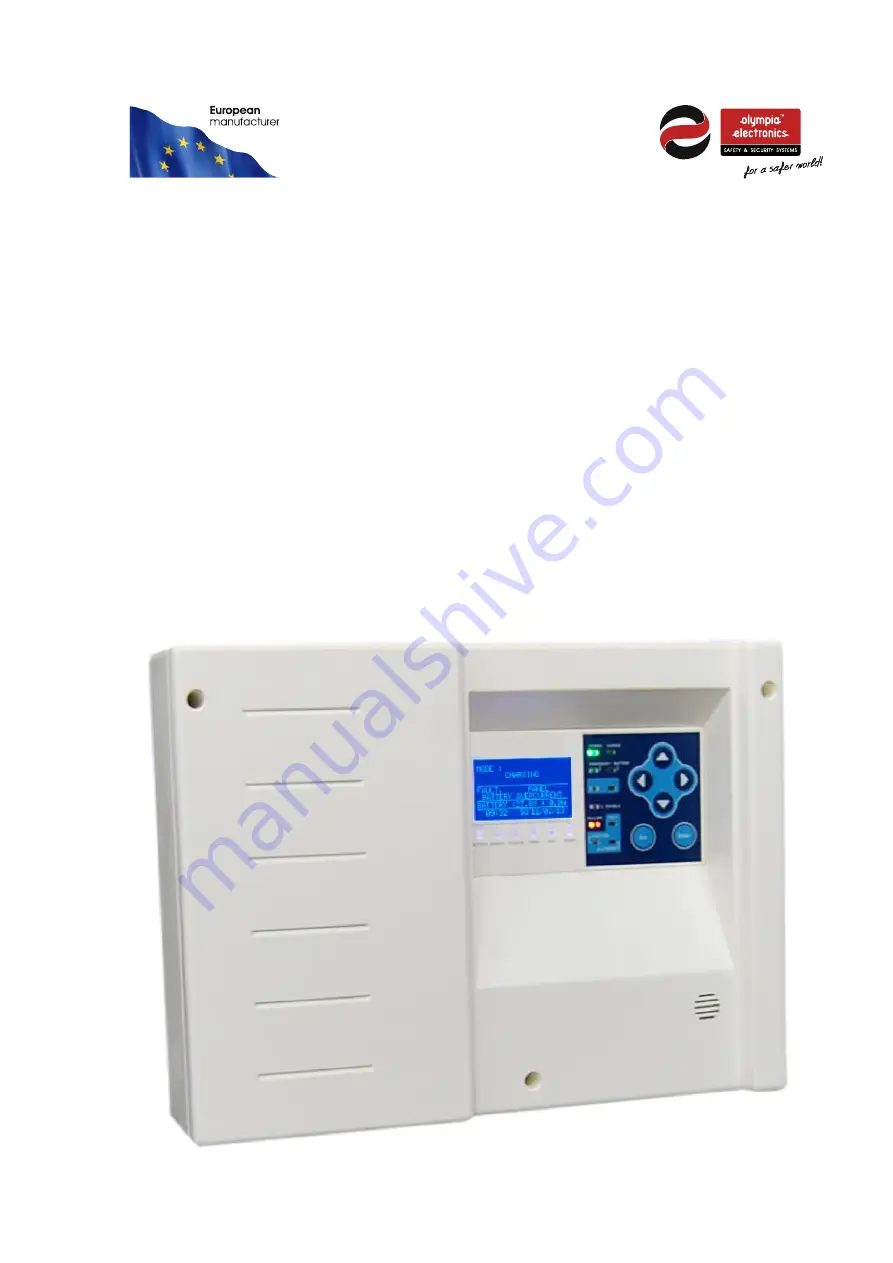
GR-6500
Addressable control panel for
Emergency luminaires
Страница 1: ...Installation guide for GR 6500 Addressable control panel for Emergency luminaires...
Страница 2: ...1 Choosing the correct cable 12 3 2 Topology of the installation 13 3 3 Addressable luminaries 13 3 4 Cross cable selection 15 3 5 Useful information for panel installation 16 3 6 Network connection...
Страница 3: ...also used in the instructions below from now on 1 2 Safety A device is not considered that it is being used correctly if the accompanying documents are not read prior to its use This product must be...
Страница 4: ...ULT SYSTEM led is on when there are faults at the system microcontroller FAULT ZONE led is on when there are faults in a zone FAULT OUT led is on when there are faults in the OUT signal FAULT POINT le...
Страница 5: ...in fault state either If any fault is found it s displayed on this section An update is made every few seconds to display all faults On the figure below you can notice that the panel is in fault state...
Страница 6: ...ES OFF IN EMERGENCY Figure 2 4 The first option CURRENT FAULTS appears only if there are faults in the panel By pressing ENTER you have two options SHOW FAULTS and RESET FAULTS see figure below Figure...
Страница 7: ...f inhibit function is enabled the luminaires will not light when the mains power fails During emergency mode the option OFF IN EMERGENCY appears This option turns off all emergency luminaires but only...
Страница 8: ...oint See the picture below Figure 2 8 The current address can change from UP DOWN keys The line below shows the number of the good and bad packet communications If the communication with the luminaire...
Страница 9: ...o see the last flag of the luminaire like function test capacity test inhibit mode if the battery is fully charged and the last autonomy in minutes Figure 2 10 If you press ENTER you can send commands...
Страница 10: ...UT displays the voltage of the four outputs of the loop ZONES shows which zones are in emergency disabled or have faults POINT shows the configuration of each address With UP DOWN keys you can scroll...
Страница 11: ...the battery to the panel DISCONNECTED the point at this address is not communicating with the panel Check the communication cables and the point at this address if they have any connection problems N...
Страница 12: ...oosing the correct cable The cable between the panel and the GR 6057 modules must have the following specifications 1 2 core twisted pair cable Normally the cables are unshielded but if the cable pass...
Страница 13: ...is 250 The panel has 4 outputs Z1A Z1B Z1C and Z1D The ideal connection is a loop connection topology between the above outputs For example the installation can start from Z1A and finish at Z1B with t...
Страница 14: ...R 26 GR 316 30L ADR 27 GR 938 4P ADR 28 GR 938 6P ADR 29 GR 939 4P ADR 30 GR 939 6P ADR 31 GR 938 15L ADR 32 GR 938 30L ADR 33 GR 939 15L ADR 34 GR 939 30L ADR 35 GR 576 L ADR 36 GR 1009 24L ADR 37 SL...
Страница 15: ...rent of the installation is calculated by adding the total current consumption of each device in normal operation If in any condition we exceed the current limit of 250mA we must install a second GR 6...
Страница 16: ...locate where a fault or a shortcut occurs If the installation is in an industrial place or the loop passes near a motor or ballasts or other devices which does not comply to CE in radiation activity...
Страница 17: ...g Relay 2 Activated when the panel is in emergency mode Relay 3 Activated when there are not any faults in the panel 3 8 USB connection At the right bottom corner of the panel PCB there is a mini USB...
Страница 18: ...stallation External cables must be connected using the cable entries or knockouts provided When routing external cables inside the panel they must be kept as short as possible Cables must be routed cl...
Страница 19: ...1000 You can see a figure of the enter code screen below With Up Down keys you change the digit Right Left keys you move to the next digit If the code is correct you enter the technician menu which h...
Страница 20: ...ures when the function test takes place See paragraph 4 2 SET CAPACITY TEST configures when the capacity test takes place See paragraph 4 3 MAKE A CAPACITY TEST makes or stops a capacity test RESET DE...
Страница 21: ...EVERY FRIDAY EVERY SATURDAY Figure 4 16 First you choose how often the function test takes place from daily to once a week and then you choose the exact time At the function test the panel will send a...
Страница 22: ...4 18 It is also possible to stop a capacity test from the same menu see figure above 4 4 Ethernet menu At the Ethernet menu you can set the Ethernet parameters ETHERNET ETHERNET PCB IP ADDRESS RESET E...
Страница 23: ...is required The IP address of the system is entered in the address bar of the browser e g http 10 0 1 152 The IP address can be found at menu INFORMATION NETWORK See the main screen bellow Figure 5 2...
Страница 24: ...Loop circuit The maximum number of addressable modules connected to the panel is 250 24V output General outputs with a 24VDC 300mA rating Output Relay 3 relay outputs with volt free contacts NC C NO M...