

9234
60000
_09_00
1
1
1
1
1
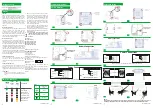
Luminaire
Decorative Bezel
Mounting accessories
Manual
Package Contents
General
1
923
460000
_09_00
1
2
9234
60000
_09_00
1
Surface Mounting
Suspended Ceiling
2
9
2
1
1
8
7
8
7
3
4
4
14,5x14,5
Installation Instructions
5
6
5
6
The Automatic Autonomy Test is conducted every 6
months and measures the device’s back up
operation and emergency duration. This test
includes all functions of the Manual Autonomy Test.
Manual
Operational
Test
Automatic Autonomy Test
o
These devices are used indoors
(
ta 40 C
)
in places
where emergency luminaires are needed. Each
device must be permanently connected to mains
power supply
.
In normal operation the battery is
charging. In case of a mains power supply failure,
the device enters emergency mode and the
illumination LED turns on. When the mains power
supply is restored the device turns to normal
operation.
Automatic Operational Test
T
his test includes all the operations that are
provided in Manual Operational Test and is
conducted automatically every 15 days and lasts 3
seconds.
1. Operations for installation, maintainance or
testing must be done by authorized personnel
only
.
Manual
Autonomy
Test
A duration test can be conducted by holding the A-
1900 card steadily for 5 to 10 seconds.
In order to be
performed, the mains power supply and the battery
must be fully charged (green LED steady ON).
The
luminaire enters emergency mode, the charge LED is
turned OFF and the Battery Fault led starts to blink.
Its
duration is the stated autonomy duration of the
luminaire
.
If at the end of the test
,
the autonomy is low
then the Battery Fault LED will be ON. If the result of
the test is good then the luminaire enters
normal
mode and the Charge led starts
blink
ing
until the
batteries are fully charged.
ΑΤΤΕΝΤΙΟΝ!
!!
GENERAL
This test can be done
by using the
A-1900 card
and
lasts for 3 seconds
.
The light source and the
emergency circuit of the device are tested. The
manual test can be conducted only if the mains
power supply and the battery are connected. During
this test period the LAMP TEST LED will blink. The
battery must have adequate charge.
CN9: Battery Connector
4. In case of battery or lamp replacement, these
must be replaced by parts with same type, by the
manufacturer or by a competent person.
3. The device must be connected to the mains
power supply through a fuse that is dependent
on the total line’s power load.
CN5: Non User Connector
CN1: Power Supply
CN11: Non User Connector
180:
3hours duration
X:
Self contained
Connectors:
6.
I
s not allowed to discard batteries into
t i
common trash bins, they must be discarded
only
in battery recycling points. Do not
incinerate.
2. Always use in any case round mains cable
,
with a
diameter
of 5
-
10mm (H05RN-F type 2x1mm²
or
any
other type
,
at least
equal
to it’s mechanical
and electrical properties). ATTENTION!! The cable
must not be deformed in any way (This
requirement is important to ensure the
ΙΡ
rating).
5. In case of inactive use for a period greater than 2
months, disconnect the battery by pulling out the
battery’s connector.
CN2: Non User Connector
1:
Maintained (*)
A:
Including test device
480:
8hour
(*)
Maintained operation: The luminaire lights its
illumination source, when it is powered by the mains
power supply or not
.
E:
With non-replaceable lamp(s)
Non Maintained operation: The luminaire lights its
illumination source,
only in power supply’s failure.s
duration
F:
Automatic test gear complying with IEC 61347-2-7
denoted EL-T
LABELING EXPLANATION:
60:
1hour duration
NOTE:
LED= Light Emitting Diode
Battery Connection
Battery Connection
9
11
3
10
NOTE!!
After finishing the installation you must power the luminaire for at least 24 hours in order to
completely charge the battery. The rated autonomy duration can be achieved after that time.
X 1
6 0
A E F
Ν
for neutral,
L
for live wire and
L1
for the maintained operation.
Ν
for neutral,
L
for live wire and
L1
for the maintained operation.
Power Connections
Power Connections
2
1
3
L
N
External
switch
Controlled operation of the lamp
a)
L
L1
N
L
N
External
switch
Controlled operation of the lamp
a)
L
L1
N
L
N
Link
Permanent maintained operation
b)
L
L1
N
L
N
Link
Permanent maintained operation
b)
L
L1
N
Description
Indications
LED Status
BATT.
FAULT
(
yellow
)
LAMP
FAULT
(
red
)
CHARGE
(
green
)
Fully charged
Charging
Battery fault or
emergency mode
Operational test
Operational failed
Autonomy test
Duration fault
Note
:
Permanently
ON
Blink
Indifferent
Off
B A PE L1 N
L
Adhesive-Backed
Zip Tie Anchor
Tire up
B A PE L1 N
L
Adhesive-Backed
Zip Tie Anchor
Tire up