background image

Page


2 of


5

921477000_0

9

_00

5

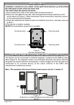
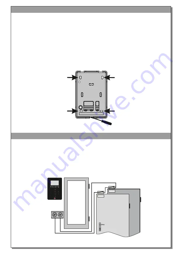
The device can be connected to external magnetic contacts via the 

CN

1

 terminal


block

(Figure 3). If a magnetic 

contact

 is connected to this input, the device 

will 

send 

signal

 to the panel

 everytime the magnetic contact is triggered

.

If

 the contact is not 

connected  to  an  external  device,  at  the 

cable 

terminal


of  the 

CN

1

,  the

n


manufacturer

’s cable

 must remain.

Note:

 The maximum distance of the external sensor cable is 3 meters !!!


Installation should only be carried out by 

quili

fied technicians, provided that 

the entire technical manual has been read.
To install, follow the procedure below:
1.

 Remove the 

front cover

 of the device with a wide screwdriver.

2.

 Mount the rear plastic to the wall, with the supplied mounting materials,

 to

 the


points shown in Figure 2. When an external input connection is required

,


connect

    to

 the terminal block 

of

 the base.

3.

 Insert the batteries into the device and re

-install

 the f

ront cover

, that was removed


in step 

1.

4.

 The device is ready to operate.

NOTE!!

Reverse battery protection is provided

.

INSTALLATION

INSTALLATION

CONNECTION WITH EXTERNAL MAGNETIC

 CONTACT

CONNECTION WITH EXTERNAL MAGNETIC

 CONTACT


CN

1

Figure 3.

Example of a wireless keyboard connection

 with

BS-477

Figure 2.

Wireless keyboard base

Mounting points

Mounting points

Mounting points

Mounting points

Содержание BS-477

Страница 1: ...OF COVER PROTECTION PRODUCED IN ACCORDANCE WITH COMPLIES WITH OPERATION TEMPERATURE RANGE CONSTRUCTION MATERIALS DEVICE DIMENSIONS LxWxH TYPICAL WEIGHT GUARANTEE 2 years ο 10 to 40 C COMMUNICATION FREQUENCY COMMUNICATION RANGE 868 MHz About 200m open area ABS PC 205gr 150 6 x 100 6 x 30 6 mm EN 50131 1 CLC TS 50131 2 2 EN 50131 5 3 classification grade 2 ETSI EN 300220 EN 50130 4 EN 55022 EN 60950...

Страница 2: ...l has been read To install follow the procedure below 1 Remove the front cover of the device with a wide screwdriver 2 Mount the rear plastic to the wall with the supplied mounting materials to the points shown in Figure 2 When an external input connection is required connect to the terminal block of the base 3 Insert the batteries into the device and re install the front cover that was removed in...

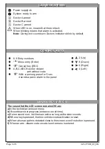
Страница 3: ... or code to enter menu is entered LED INDICATIONS LED INDICATIONS CONTROL KEYS CONTROL KEYS DEVICE ACTIVATION DEVICE ACTIVATION Power supply ok System ready to arm Sector A armed Sector B armed Sector C armed When LED is on means that there is fault When blinking means that alarm is activated Note During exit countdown Sectors indicators blink by default B C A 0 9 Entry numbers Menu entry Enter Ca...

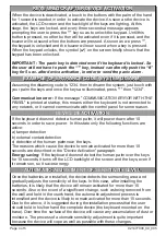
Страница 4: ...activated the LCD screen and the backlight of the keys are lighting At this stage the keys are locked and every three seconds a message appears prompting the user to press the key so as to unlock the keypad Until this button is pressed no other button will be activated even if it is pressed and the buzzer will not sound when the buttons are pressed As soon as we press the keypad is unlocked and th...

Страница 5: ...rves the right to repair or to replace the returned goods and to or not charge the buyer depending on the reason of defection Olympia Electronics reserves the right to charge or not the buyer the transportation cost HEAD OFFICE 72nd km O N R Thessaloniki Katerini P C 60300 P O Box 06 Εginio Pierias Greece www olympia electronics gr info olympia electronics gr WARRANTY WARRANTY The wireless keyboar...

Отзывы: