background image

E-10

17. Configuring other options

(1) If any of the following options are installed, refer 

to the “Configuration procedures” of the installa-

tion manual for each option and configure the 

option(s).

• Dual Scan Document Feeder DF-704

• Reverse Automatic Document Feeder DF-629

• Stamp Unit SP-501

• Fax Kit FK-514

• Punch Kit PK-520/PK-519

• Upgrade Kit UK-212/UK-211

• Paper Feed Cabinet PC-410

• Large Capacity Unit LU-302

• Local Interface Kit EK-609

• Security Kit SC-508

• Hard Disk HD-524

• Authentication Unit AU-201S/AU-102

• Clean Unit CU-101

• Network Fax

Note:

The installation manual for each option contains 

the following caution for completion of settings: 

“When displayed the Service Mode screen, be 

sure to turn off the power after exiting the Service 

Mode screen and wait for 10 seconds or more 

before turning on” However, since all settings are 

made at the same time in accordance with “20. 

Restarting the machine” in this installation manual, 

you do not need to turn the power off and on again 

after configuring each individual option.

(2) Exit from the Service Mode and return to the ini-

tial screen.

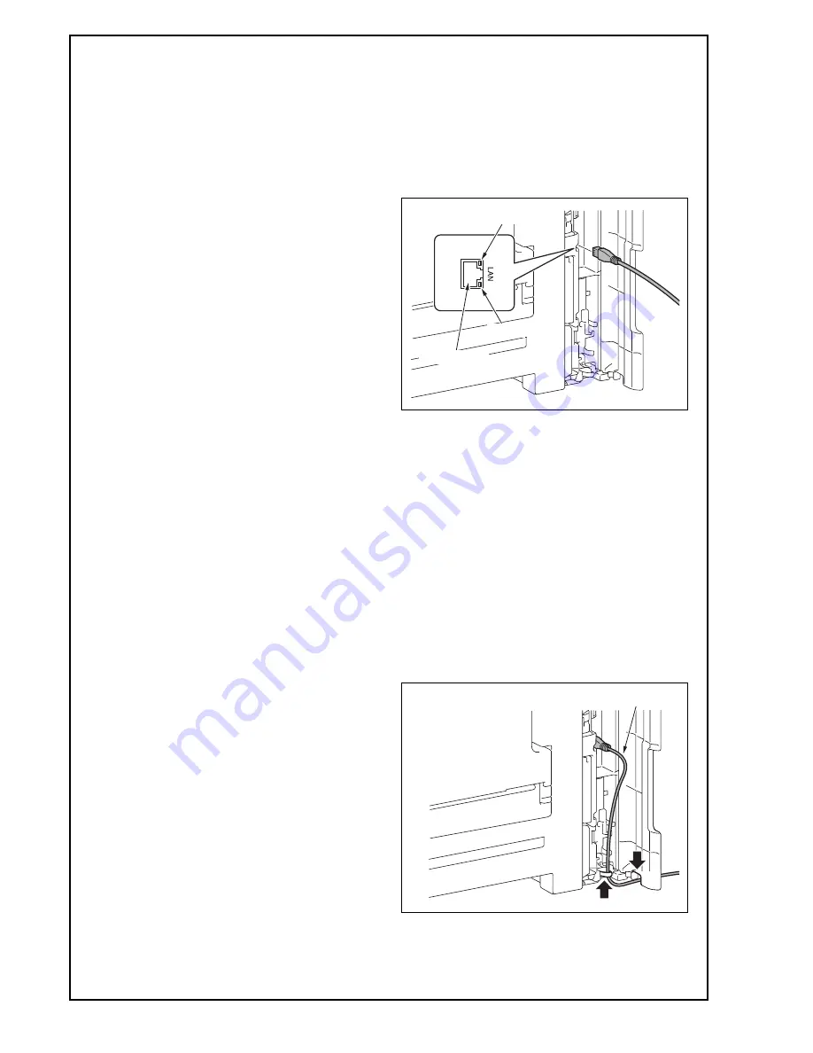
18. Connecting the network cable

(1) Connect the main body and networking equip-

ment (HUB) using the network cable.

Note:

The following shows the recommended network 

cables that correspond to each communication 

speed.

• 10BaseT/100BaseTX: Category 5

• 1000BaseT: Category 5E, Category 6

(2) Check LEDs for lighting conditions.

LED1: 

Should light up steadily if the link network con-

nection has been made.

LED2: 

Should blink according to the communications 

status of the ACT network.

(3) Route the network cable.

<When adding no paper feed options>

a) Route the network cable through the harness

guide and pass it through the notch.

Note:

Leave an appropriate amount of slack in the por-

tion of the cable between the plug and the harness 

guide in a manner which does not interfere with 

the opening and closing of the cover.

Networkport

LED2

LED1

Leave an appropriate amount of slack.

Installation Manual

Y

117020-9

Содержание d-Color MF304

Страница 1: ...85 kg 187 3 8 lb Note For the detailed installation procedures for each option follow the instructions given in the corresponding installation manual and perform the procedures correctly When placing...

Страница 2: ...your fin ger or the stylus pen supplied with the machine If you touch the panel using your nail or a pen tip instead of using your finger or the stylus pen the touch panel does not respond normally P...

Страница 3: ...andles on the right and left sides as shown in the illus tration and keeping it level 2 Refer to the installation manual for the Paper Feed Cabinet and follow the Installation Proce dures Note If inst...

Страница 4: ...e sure that the transfer roller assy is secured in place In the case of NG press the transfer roller assy into place so that it is secured as shown in OK Save the packaging materials removed in this a...

Страница 5: ...the protective tapes from the inside of the tray 2 and remove accessory parts 8 Remove the locking screws 9 Attach the supplied caps A and B 10 Remove the protective sheets 11 Open the front door 12...

Страница 6: ...places 15 Release the lever of the drum unit K 16 Slightly slide the drum unit K out and remove the protective tape 17 Slide the drum unit K into the machine 18 Lock the drum unit K with the lever 19...

Страница 7: ...the blue label position of the toner cartridge is matched with the one of the machine side 3 Push the toner cartridge all the way in and rotate it clockwise to lock it Note Make sure that the toner c...

Страница 8: ...A 4 Attach the supplied connector cover to the machine One supplied screw B 5 Attach the supplied duct cover 11 Connecting the power cord 1 Connect the power cord 2 Fit the supplied cord clamp over t...

Страница 9: ...way 5 Touch END 15 Unit change Note This function allows the user to select the type of message that will appear when the replacement time arrives for each of the different units 1 Select the Unit Cha...

Страница 10: ...the machine in this installation manual you do not need to turn the power off and on again after configuring each individual option 2 Exit from the Service Mode and return to the ini tial screen 18 Co...

Страница 11: ...ed and make settings as required 1 Select the function to be used as follows Menu Utility Administrator Settings Enter the Administrator Password Network Settings TCP IP Settings IPv4 Settings 2 Touch...

Страница 12: ...ay See the User s Guide CD for instructions on setting paper in each tray and configuring the paper types 23 Installing the user s guide holder Install the user s guide holder 24 Affixing the panel sh...

Страница 13: ...nd hinge cover left Two screws supplied with the original cover 3 Install the original cover No Name Shape Q ty 1 Original cover 1 2 Hinge cover right 1 3 Hinge cover left 1 4 Screw 2 Keep this bag aw...

Отзывы: